
A Class A office building’s HVAC system is not a utility. It is a legal instrument. The ventilation performance specifications written into tenant leases, LEED certification documentation, and ASHRAE 62.1 compliance filings create a contractual obligation to deliver design-intent outdoor air volumes to every occupied zone. Particulate accumulation in distribution ductwork does not merely degrade air quality. It constitutes a measurable deviation from those obligations.
The air duct cleaning equipment deployed in a Class A environment must meet a different specification than the equipment used in industrial or residential contexts. The constraint is not just airflow. It is logistics, acoustics, documentation chain, and tenant relations. This protocol addresses all four.
The Green Building Standard: LEED Credits and Indoor Environmental Quality (IEQ)
LEED v4 and v4.1 BD+C (Building Design and Construction) and O+M (Operations and Maintenance) rating systems both allocate credits under the Indoor Environmental Quality (EQ) category. The specific mechanism most directly affected by duct system cleanliness is the EQ Credit: Indoor Air Quality Assessment.
How Duct Contamination Affects LEED Credit Eligibility
LEED EQ Credit: IAQ Assessment under v4 BD+C (worth up to 2 points) requires either a flush-out procedure or baseline IAQ testing before occupancy. For existing buildings pursuing LEED O+M recertification, ongoing IAQ performance is tracked against ASHRAE 62.1 design targets.
The logical chain:
- Particulate accumulation on duct interior surfaces continuously re-entrains into the airstream under normal operating velocities (600-900 FPM in supply trunks).
- Re-entrained particulate increases PM2.5 and PM10 concentrations in occupied zones.
- Elevated particulate concentrations register in IAQ assessment sampling as failing results.
- Failing IAQ assessment results invalidate the credit and, under O+M recertification, can reduce the facility’s overall LEED score.
The financial implication for asset managers: a Class A office building’s LEED certification is a direct input to its cap rate calculation. Institutional investors apply a documented 3-7% premium to certified green buildings over equivalent non-certified stock in the same submarket. Losing a LEED certification tier due to IAQ non-compliance is a valuation event, not a maintenance oversight.
WELL Building Standard Intersection
For facilities pursuing WELL v2 certification concurrently with LEED, the Air concept requires particulate matter performance at the diffuser level, not the air handler level. This means duct system cleanliness is evaluated at the terminal device, the point closest to the occupant. A clean AHU with contaminated distribution ductwork does not satisfy WELL Air Feature A02 (Smoke-Free Environment and PM2.5 Limit) in practice, even if it satisfies it on paper.
ASHRAE 62.1 Ventilation Mechanics: Why Dirty Ducts Starve Office Zones
ASHRAE Standard 62.1 (Ventilation for Acceptable Indoor Air Quality) governs minimum outdoor air delivery rates in mechanically ventilated buildings. The current edition specifies outdoor air delivery in CFM per person and CFM per square foot for office occupancy categories.
Typical Class A office specifications:
- 5 CFM per person plus 0.06 CFM per square foot of net occupiable area.
- A 25,000 SF floor plate at 150 SF per person (167 occupants) requires a minimum outdoor air delivery of 2,335 CFM to that floor.
Duct contamination attacks this number from two directions.
Restriction-Side Failure: Pressure Drop Accumulation
Accumulated particulate on duct interior surfaces increases the effective roughness coefficient of the distribution system. This is quantified in duct design using the Darcy-Weisbach equation, where friction factor is a direct function of surface roughness relative to hydraulic diameter.
In practical terms: a heavily contaminated 18-inch round main trunk with a measured particulate film of 0.025 inches exhibits an elevated friction factor that increases static pressure drop by approximately 8-15% over a clean-duct baseline across a 100-foot run. The AHU fan compensates by running at higher static pressure to maintain design airflow. Energy consumption increases. If the fan is operating at or near its design maximum, zone airflow drops.
Fan-powered VAV terminal boxes are particularly sensitive to this failure mode. These devices draw both primary supply air and induced plenum return air. When supply duct static pressure drops below the terminal box design operating point, primary air volume decreases and the fan compensates with a higher proportion of recirculated plenum air. Outdoor air delivery to the zone falls below 62.1 minimums without triggering any alarm.
Induction Unit Fouling: The Hidden Compliance Failure
Four-pipe fan coil units and induction units in perimeter zones present a secondary contamination pathway. These terminal devices draw return air directly from the occupied space across a coil and re-condition it. Their internal passages and coil surfaces accumulate dust and particulate at a faster rate than the main distribution system because they operate in direct contact with room air, not filtered supply air.
A fouled induction unit coil reduces the device’s sensible cooling capacity and increases the fraction of occupied air that bypasses the coil without conditioning. The practical result is zone-level temperature drift, increased complaints, and cascading calls to increase supply air volume from the AHU, further stressing the distribution system.
Comprehensive ASHRAE 62.1 compliance in a Class A facility requires cleaning the distribution trunk system, the VAV terminal boxes, the induction units, and the AHU coil sections in a single coordinated scope. Cleaning the trunk system in isolation without addressing the terminal devices produces a clean upstream system delivering air into fouled final-stage components.
Logistical Architecture: Why Class A Properties Demand Portable Extraction
This is the constraint that eliminates truck-mount vacuum systems from Class A high-rise work. It is a physics argument, not a preference.
The Static Pressure Penalty on Vertical Runs
A truck-mount vacuum system is engineered to operate with hose runs of 150-300 feet at grade level or minimal elevation change. The system’s static pressure rating is calculated for this condition.
Place that system on the street outside a 20-story office building and run the collection hose up through the service elevator shaft or stairwell to the 15th floor mechanical room. The vertical lift alone imposes a static pressure penalty of approximately 0.433 inches of water column (WC) per 10 feet of vertical rise. A 150-foot vertical run to the 15th floor imposes a static pressure demand of 6.5 inches WC before accounting for hose friction losses.
Most truck-mount systems are rated at 8-12 inches WC at the hose inlet under zero-flow conditions. With a 150-foot vertical run plus 100 feet of horizontal duct run on the floor plate, the total static pressure demand routinely exceeds the system’s rated operating envelope. Airflow collapses. The contractor is operating a truck-mount system at 600-900 CFM effective output, not the rated specification.
The Freight Elevator Constraint
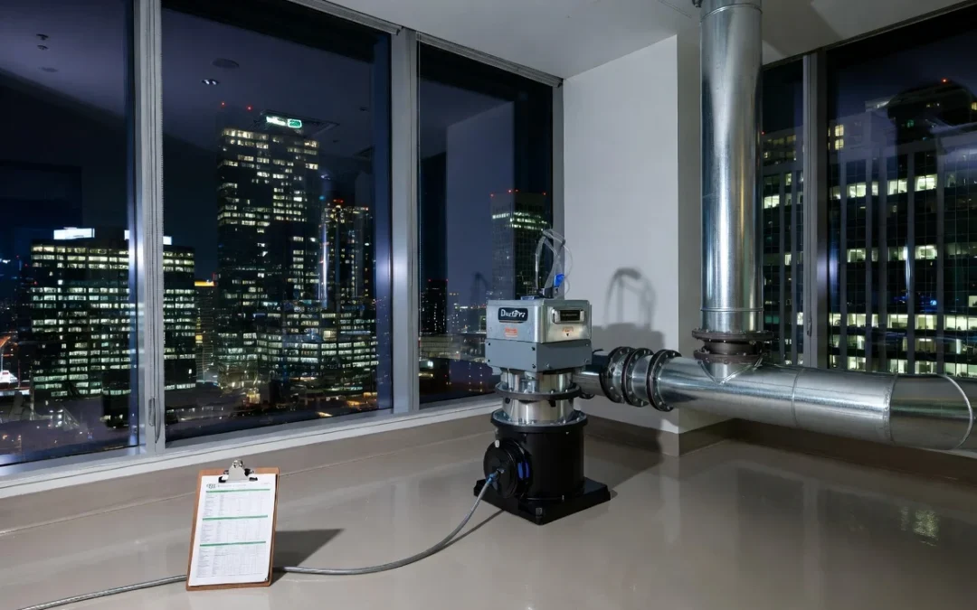
Class A building service freight elevators are rated at 2,500 to 3,500 lbs capacity with cab dimensions typically in the range of 5 feet wide by 8 feet deep by 7 feet tall. A truck-mount vacuum system that must be transported to an interior mechanical room requires modular components that fit within these dimensions and weight limits.
The DuctPro Tri-Motor portable system is specifically engineered for this constraint. The high-impact cabinet is designed for single-person transport through standard 36-inch service corridors and loads within the freight elevator weight envelope without requiring special rigging or building management pre-approval. See the detailed physical specification breakdown in our portable duct cleaning system architecture resource.
This logistical reality is why the performance gap between portable and truck-mount systems inverts in high-rise commercial work. A 5,000 CFM portable system delivering full output at the 15th floor mechanical room outperforms a 12,000 CFM truck-mount operating at 25% effective output through a degraded vertical hose run.
Mixed-Use and Multi-Tenant Considerations
Class A office towers increasingly incorporate ground-floor retail and food-service tenants. The ventilation system design for these mixed-use configurations requires careful scope delineation. The exhaust management standards for kitchen and food-service zones operate under a completely different set of mechanical and chemical protocols compared to standard office ventilation. For a detailed contrast of those requirements, see our restaurant duct cleaning standards protocol.
For the office floors specifically, the absence of grease contamination does not mean the duct system is clean. Construction dust, drywall particulate from tenant improvement cycles, fibrous insulation fragments from duct liner disturbance, and accumulated biological load in humidification zones are the primary contamination categories in Class A office ductwork.
Operational Protocols for Off-Hours High-Rise Execution
A Class A office building has one non-negotiable operational constraint: occupied floors cannot be in active HVAC cleaning scope during business hours. The reasons are acoustic, contractual, and health-related simultaneously.
The Execution Window
Standard off-hours window: 10:00 PM to 6:00 AM. This provides an 8-hour working window that must accommodate:
- Equipment staging from the loading dock to the target floor via freight elevator.
- HVAC system shutdown and isolation on the target zone.
- Full cleaning scope execution including agitation, extraction, and terminal device service.
- System restart and functional verification before occupied hours.
- Equipment strike and loading dock clearance.
An 8-hour window is tight. It requires a scope that can be executed to completion without equipment failure or mid-job restarts. This is where Tri-Motor redundancy becomes a contract-level risk management tool.
Tri-Motor Redundancy as Operational Insurance
A single-motor portable vacuum unit that experiences motor failure at 3:00 AM on the 18th floor of an occupied building has no recovery path within the execution window. The floor is partially cleaned. The HVAC system cannot be safely restarted with exposed duct sections. Morning occupancy begins at 8:00 AM. The building engineer is now managing a tenant relations event and a potential lease compliance issue simultaneously.
The DuctPro Tri-Motor system’s three independent motors allow continued operation if one motor requires maintenance mid-job. At two-motor operation, the system maintains 3,333 CFM output: above the transport velocity threshold for office particulate in standard trunk dimensions and sufficient to complete the floor-scope extraction within the execution window.
This is not a theoretical backup. Building engineers who have managed HVAC cleaning contracts understand that a contractor’s equipment reliability is a project schedule risk. Specifying a system with documented motor redundancy reduces that risk to a manageable level.
Zone Isolation Protocol for Multi-Zone Floor Plates
Class A floor plates commonly run 20,000 to 40,000 SF per floor with 4 to 8 VAV zones fed from a central AHU or multiple terminal air handling units. Cleaning the full floor plate in a single shift requires a zone isolation strategy that allows sequential extraction without re-contaminating already-cleaned zones.
The sequence:
- Identify the AHU supply trunk origin and map all zone branch takeoffs.
- Isolate Zone 1 (furthest from AHU) by closing dampers at the branch takeoff point.
- Establish negative pressure in Zone 1’s distribution run from the terminal end back toward the branch damper.
- Execute agitation and extraction in Zone 1’s full branch run and all terminal devices on that branch.
- Seal the cleaned zone before opening Zone 2.
- Progress branch by branch back toward the AHU supply trunk.
- Clean the main supply trunk last, from the AHU discharge plenum to the last branch takeoff.
This sequencing ensures that agitation of the main trunk, which will generate the highest particulate displacement event of the entire job scope, occurs after all branch zones are already cleaned and sealed. The full sequence and documentation requirements for multi-zone commercial floor plates are detailed in our commercial air duct cleaning process reference.
Acoustic Containment
Mechanical agitation tools operating inside ductwork generate structure-borne noise that transmits through the duct wall and building structure. In a high-rise where multiple floors are occupied during evening hours (security, data center operations, 24-hour trading operations), acoustic containment is an active requirement.
Mitigation measures:
- High-velocity air whips generate lower impact noise than rotary contact brushes. For office particulate (no grease, no caked deposits), air whip agitation combined with 5,000 CFM transport velocity achieves extraction without requiring contact tooling on most duct sections.
- Work sequencing should progress from lower floors to upper floors when possible, reducing structure-borne transmission to occupied zones below.
- Notify building security and 24-hour floor tenants in writing 72 hours prior to execution with an expected acoustic impact window.
Project Verification and Closeout Documentation for Facility Directors
The cleaning scope does not close when the equipment leaves the building. Documentation production is a deliverable with equal standing to the physical cleaning work.
NADCA ACR Standard Compliance
The NADCA Assessment, Cleaning, and Restoration (ACR) Standard is the industry benchmark for duct cleaning scope verification. For Class A properties, NADCA ACR compliance documentation provides the third-party-validated evidence required for:
- LEED O+M recertification IAQ credit submissions.
- Tenant lease compliance verification upon renewal.
- Insurance carrier documentation of preventive maintenance activity.
- Capital expenditure justification for HVAC asset management reporting.
The ACR standard defines acceptable cleanliness as a visual inspection standard supplemented by a surface particulate test (typically a tape lift or vacuum filter weight method). Post-cleaning results must show no visible debris on interior duct surfaces under raking light inspection and surface contamination below 0.75 milligrams per 100 square centimeters by the vacuum test method.
Required Closeout Package
The post-service documentation package for a Class A office building scope should include:
Pre-Service Documentation:
- Video borescope inspection of representative duct sections (minimum one per zone, logged by zone designation and access panel ID).
- Photographic record of all terminal device conditions before cleaning.
- AHU coil condition photographs before coil cleaning scope (if included).
Post-Service Documentation:
- Post-cleaning video borescope footage at the same documented locations.
- Surface particulate test results by zone with NADCA ACR threshold comparison.
- HVAC system operational verification: measured supply air volumes at terminal devices post-cleaning versus pre-cleaning baseline (CFM by zone, documented with balometer readings).
- Filter replacement record (all system filters should be replaced after cleaning scope, not before, to avoid fouling new media with displaced particulate).
Compliance Attestation:
- Signed technician certification confirming NADCA membership and ACR standard adherence.
- Equipment specification sheet for the vacuum system used, including rated and measured CFM output.
- Chemical product data sheets for any sanitizing agents applied, confirming compatibility with duct materials and occupant safety following re-occupancy.
The IAQ Measurement Baseline
For facilities tracking IAQ performance under WELL v2 or LEED O+M, pre- and post-cleaning PM2.5 spot measurements at representative diffuser locations provide a before/after performance delta that directly supports credit documentation. A standard IAQ handheld meter (PurpleAir, TSI DustTrak, or equivalent) logging at 5-minute intervals during the first occupied morning following cleaning completion will capture the immediate post-cleaning baseline. This data is the most direct evidence of cleaning impact available to a facility director.
Conclusion: Protecting Asset Value with Engineering-Grade HVAC Decontamination
A building engineer managing a Class A asset is accountable for three simultaneous obligations: code compliance (ASHRAE 62.1), green certification performance (LEED, WELL), and occupant productivity metrics that increasingly appear in tenant ESG reporting. All three connect directly to HVAC system performance, and HVAC performance degrades measurably and predictably as particulate accumulates in the distribution system.
The equipment specification for this work is not a procurement decision. It is a performance contract. 5,000 CFM portable extraction that operates at full output from an interior mechanical room, with motor redundancy to protect an 8-hour execution window, with a three-stage HEPA filtration system capturing displaced particulate at 99.97% efficiency at 0.3 microns: this is the specification that closes the gap between a cleaning service record and a documented improvement in zone-level air quality.
The closeout documentation produced by an engineering-grade scope is also an asset management instrument. It supports lease renewals, green certification renewals, and capital planning decisions with quantified data, not maintenance logs.
Review the full equipment configuration and technical specifications for commercial high-rise applications at DuctPro air duct cleaning systems.