
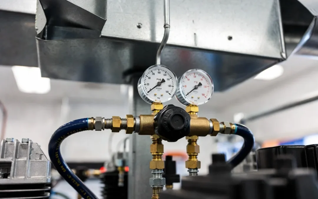
Pressure means nothing without volume. A compressor rated at 150 PSI is useless for duct agitation if it cannot sustain airflow under load. This is the single most misunderstood spec on a contractor’s equipment sheet, and it is why crews running undersized compressors get inconsistent agitation results despite buying a “high pressure” unit.
The operational goal is not peak tank pressure. It is dynamic pressure, the pressure your tool actually sees while air is flowing continuously against resistance. Static tank numbers on a spec sheet describe a compressor sitting idle. The moment you pull the trigger on an air whip or skipper ball, that number starts dropping, and how much it drops determines whether your agitation tool actually has enough energy to break debris bonds off the duct wall.
Crews standardizing on air duct cleaning equipment treat PSI and CFM as a paired spec, never evaluated in isolation. A compressor with excellent PSI and inadequate CFM will stall under continuous tool demand. A compressor with excellent CFM and inadequate PSI will move air without enough force to shear bonded material. Both numbers have to clear their thresholds simultaneously.
Section 1: The Physics of Pneumatic Agitation
Static Pressure vs. Dynamic Pressure
Static pressure is what your gauge reads with the compressor tank full and no air flowing. It is a stored-energy number, not a working number.
Dynamic pressure is what your tool sees at the point of use, under continuous flow, after line losses. This is the number that determines cleaning performance, and it is always lower than static pressure the moment a tool is engaged.
A compressor advertised at 150 PSI static may deliver 80 to 90 PSI dynamic at the nozzle once you account for regulator settings, hose losses, and continuous draw. If your agitation tool requires 100 PSI minimum to function correctly, that spec sheet number was never achievable in the field.
Discharge Velocity at the Nozzle
Nozzle discharge velocity follows the square-root relationship between pressure differential and orifice area:
$$V_{discharge} \propto \sqrt{\frac{2 \Delta P}{\rho}}$$
Where:
- $\Delta P$ = Pressure differential across the orifice
- $\rho$ = Air density
Velocity scales with the square root of pressure, not linearly. This means a compressor that loses half its rated PSI to line drop does not lose half its discharge velocity; it loses roughly 30%. While that sounds safe on paper, it performs poorly in the field because that remaining velocity still has to overcome heavy debris cohesion, not just move ambient air.
Overcoming Cohesive and Structural Debris Bonding
Debris adhered to sheet metal walls exhibits two distinct bonding behaviors:
- Cohesive Bonding: This occurs where compacted particulate holds itself together through ambient moisture and mechanical compression. This is highly common in older systems with years of un-remediated accumulation.
- Structural Bonding: This occurs where debris has partially fused to the duct wall through mold growth, corrosion byproducts, or adhesive residue from historical sealant work.
Cohesive bonds shear at lower discharge velocities. Structural bonds require sustained high-velocity impact, repeated passes, or mechanical brushing in combination with a pneumatic blast. An undersized compressor will not fail obviously; it will appear to clean the surface layer while leaving the bonded base layer fully intact. This is the exact failure mode that generates a callback three weeks later.
Section 2: Determining the Optimal PSI and CFM Thresholds
Pneumatic Air Whips
- Minimum Dynamic Pressure: 90 PSI
- Minimum Sustained Airflow: 20 CFM per whip in continuous operation
- Failure Symptom: The whip loses its characteristic snap and drags lazily along the duct wall instead of violently striking it.
High-Velocity Skipper Balls
- Minimum Dynamic Pressure: 100 to 120 PSI
- Minimum Sustained Airflow: 25 to 30 CFM per ball
- Failure Symptom: The ball loses forward propulsion and stalls mid-run, particularly on vertical drops or transitions.
Forward-Blast Nozzles
- Minimum Dynamic Pressure: 80 to 100 PSI
- Minimum Sustained Airflow: 15 to 20 CFM depending on orifice diameter
- Failure Symptom: A narrow, weak discharge pattern with poor coverage width and failed particulate liftoff.
Continuous Duty Cycle Sizing
Commercial rigs running agitation tools for full shift durations need compressor sizing calculated for 100% duty cycle, not the intermittent duty cycle most rotary screw or reciprocating compressors are rated for out of the box. A compressor rated for 25 CFM at a 40% duty cycle will rapidly overheat and cycle down under continuous commercial use.
Rule of thumb: Size your compressor at 1.5 times the combined CFM demand of every tool you intend to run simultaneously, calculated at 100% duty cycle. This strategic headroom prevents continuous compressor cycling, which is the single most common cause of inconsistent PSI on job sites.
Section 3: Minimizing Friction Loss and Line Drop
Hose internal diameter is the most underestimated variable in pneumatic tool performance. Friction loss compounds with distance and inversely with the fourth power of internal diameter, meaning small ID reductions produce massive pressure penalties over long hose runs.
Pneumatic Line Pressure Drop Matrix
| Hose Internal Diameter (ID) | PSI Drop at 50 ft (100 PSI supply, 20 CFM draw) | PSI Drop at 100 ft (100 PSI supply, 20 CFM draw) |
| 1/4 Inch ID | 18 to 22 PSI Loss | 35 to 40 PSI Loss |
| 3/8 Inch ID | 6 to 9 PSI Loss | 12 to 16 PSI Loss |
| 1/2 Inch ID | 2 to 4 PSI Loss | 5 to 7 PSI Loss |
Reading the Engineering Data Correctly
A 1/4-inch air line at 100 feet can lose more than a third of its supply pressure before the air ever reaches the tool head. This is why a compressor that tests perfectly at the truck manifold with a short 10-foot hose underperforms badly on a real job site with a 75-foot drop into a mechanical room or an unexposed rooftop unit.
Practical Sizing Guidance
- Runs Under 25 Feet: A 3/8-inch ID hose is adequate for single-tool operation.
- Runs 25 to 75 Feet: A 1/2-inch ID hose is the absolute minimum requirement, especially for skipper ball operation.
- Runs Over 75 Feet: Deploy a 1/2-inch ID lead line with a secondary regulator mounted at the point of use to compensate for residual system pressure drop.
Section 4: Integrating Suction Velocity and Pneumatic Blasting
The Mass Airflow Balance Problem
Injecting high-pressure compressed air into an active negative air boundary adds mass airflow that your extraction system must absorb. A forward-blast nozzle discharging 20 CFM into a duct section under negative pressure is introducing a positive airflow event inside a closed vacuum circuit.
If extraction CFM does not exceed injected CFM by a wide margin, the negative pressure boundary weakens locally at the point of agitation, creating a brief window where contaminants escape containment. This matches the exact containment logic behind vacuum airflow performance calculations used to size extraction systems: you must size your vacuum to absorb an injected pneumatic load, not just move static ambient air.
Why Pneumatic Blast Energy Decays Rapidly
Discharge velocity from a pneumatic nozzle decays rapidly with distance from the orifice, following an inverse relationship with distance for free jet expansion. Effective cleaning energy is heavily concentrated within a short working distance of the nozzle tip—typically measured in inches, not feet. This means:
- Agitation is a highly localized event.
- Particulate capture must be downstream and completely continuous.
A physical gap between your agitation point and your effective suction capture allows dislodged debris to resettle down-line before it ever reaches the collection unit.
Practical Operational Sequencing
- Confirm Vacuum Stability: Confirm the negative air boundary is established and stable before introducing pneumatic tools.
- Position the Inlet: Position your primary extraction inlet as close as practical to the active agitation zone.
- Calculate Mass Margins: Size extraction CFM to exceed total injected compressor CFM by a margin sufficient to maintain net negative differential across the isolated zone, matching the exact containment discipline utilized in a high-level hvac zone isolation strategy.
- Monitor Taps: Monitor for any positive pressure spikes at adjacent register openings during blast sequences, which instantly indicate extraction capacity is undersized relative to injected air volume.
Pneumatic stripping power is a product of dynamic pressure and sustained volume; skip the math on line drop or compressor sizing, and you are simply moving dirt from one corner of the system to another.