
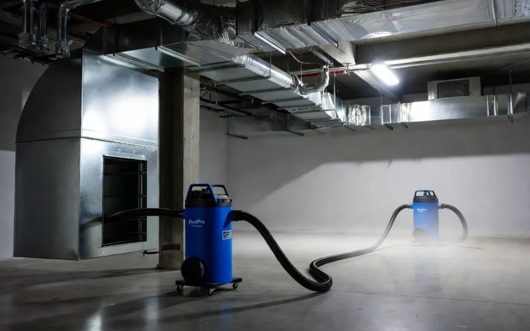
Most contractors troubleshoot weak suction by checking the machine. Filters, motor amperage, hose connections. Rarely do they walk back to where the unit is actually sitting.
That is a mistake, because equipment placement is one of the few variables in a duct cleaning job that determines system performance before the vacuum motor ever starts pulling air. A machine rated at high static pressure and strong CFM output can still underperform badly if it sits in the wrong location relative to the duct system it is cleaning. The air duct cleaning equipment used on a job matters less than most contractors assume. Placement decisions frequently matter more.
This article explains the engineering reasoning behind equipment positioning, not just where to park the truck.
Why Equipment Placement Directly Affects Vacuum Performance
Every duct cleaning system is fundamentally a pressure differential problem. The vacuum unit creates negative pressure at one end of a duct network, and atmospheric pressure at the access points pushes air toward that low pressure zone. Debris moves because air is moving, and air moves because a pressure gradient exists across the system.
Equipment placement determines how much of the machine’s rated performance actually reaches the working section of duct. Every foot of hose, every elbow, every transition fitting between the machine and the duct network consumes some portion of the available pressure differential before it ever does useful work on debris.
This is why two identical machines, positioned differently on the same job, can produce noticeably different cleaning results. The manufacturer’s rated CFM describes what the unit can produce at the inlet. It says nothing about what actually arrives at the branch duct forty feet away with three redirects in between.
Static Pressure Versus Delivered Airflow
Contractors sometimes assume that a machine’s static pressure rating is a fixed guarantee of performance regardless of setup. It is not.
Static pressure and delivered airflow exist in an inverse relationship along a fan curve. As resistance in the system increases, the machine moves further up its static pressure curve and delivered CFM drops. Poor equipment placement increases resistance in exactly this way, through longer hose runs, tighter bend radii, and additional fitting losses.
The relevant relationship can be expressed simply:
ΔP_total = ΔP_hose friction + ΔP_fittings + ΔP_elevation
Every one of these loss terms is directly influenced by where the machine sits relative to the work area. A well positioned machine minimizes each term independently. A poorly positioned machine compounds all three at once.
For a deeper breakdown of how CFM requirements are calculated for different duct configurations, see CFM Required for Professional Duct Cleaning.
Relationship Between Equipment Placement and Hose Routing
Placement and hose routing are frequently treated as separate decisions on a job site. They are not. Placement determines what routing options exist in the first place.
A machine positioned too far from the primary access point forces longer hose runs regardless of how carefully the technician routes the hose afterward. No amount of routing skill recovers pressure that was lost to distance before routing decisions even began.
The inverse is also true. A machine positioned close to the access point, but on the wrong side of a structural obstruction, can force sharper bend angles than a slightly longer but straighter run would require. Bend losses often exceed straight-line friction losses over equivalent distance, particularly at bend radii tighter than three times the hose diameter.
Placement should be treated as the first routing decision, not a separate consideration made after routing is already underway.
Pressure Loss Caused by Long Hose Runs
Friction loss in flexible vacuum hose increases with both length and velocity, and the relationship is not linear. Doubling hose length does not simply double pressure loss. Because flexible hose has a rougher interior surface than rigid ductwork, friction coefficients run higher, and losses accumulate faster per linear foot than most technicians expect.
Field data across commercial extraction setups typically shows friction losses in the range of 0.03 to 0.08 inches of water gauge per foot for standard vacuum hose, depending on hose construction and internal diameter. On a 100 foot run, that alone can consume 3 to 8 inches of water gauge before the hose ever reaches the duct opening.
This is why extending hose length to reach a distant access point is rarely a neutral decision. It is a direct trade against delivered airflow at the working end of the system.
Positioning Equipment to Preserve Transport Velocity
Transport velocity, the airspeed required to keep dislodged debris suspended and moving toward the collection point, depends on maintaining sufficient CFM through the duct cross section being cleaned. Placement affects this indirectly but significantly.
As hose length increases and pressure loss accumulates, the CFM actually delivered at the duct opening drops. If delivered CFM falls below the threshold required to maintain transport velocity for the duct size in question, debris does not fully evacuate. It redeposits partway through the run instead of reaching the collection unit.
This creates a failure mode that is easy to misdiagnose. The technician sees debris still present after a cleaning pass and assumes agitation was insufficient, when the actual cause is a placement decision made before the hose was ever connected.
Positioning equipment to minimize hose length between the machine and the working duct section is one of the most direct ways to protect transport velocity without changing anything about the machine itself.
Equipment Placement During Negative Pressure Extraction
Negative pressure extraction depends on maintaining a consistent pressure differential across the isolated duct section for the duration of the cleaning pass. Equipment placement influences how stable that differential remains as work progresses.
A machine positioned centrally relative to the zone being cleaned experiences more consistent resistance as technicians move between access points. A machine positioned at one extreme end of a long duct run experiences resistance that varies more sharply depending on which branch is currently being worked, because the effective hose length to each access point changes substantially across the job.
This variability matters because negative pressure systems are typically balanced for an expected resistance range. Placement decisions that widen that range make the extraction setup harder to keep in balance throughout the job.
For the underlying mechanics of how negative pressure is generated and maintained across a duct system, see How Negative Pressure Works in Duct Cleaning.
Residential Versus Commercial Equipment Positioning
Residential and commercial systems present different placement constraints, and contractors moving between the two often carry assumptions that do not transfer well.
Residential systems typically involve shorter total duct runs and more flexible machine positioning, since most residential trunk lines are accessible from a single exterior or garage location. The primary placement concern is usually avoiding excessive hose length to distant bedroom or basement branches.
Commercial systems introduce a different set of constraints entirely. Trunk lines run longer distances, often through mechanical rooms, plenums, or rooftop equipment areas with limited machine access. Placement decisions on commercial jobs are frequently dictated by where the machine can physically be staged, rather than where it would be positioned in an unconstrained setup. This makes pre-job site assessment considerably more important on commercial work, since placement options may be limited to one or two viable locations for the entire building.
Multi-Story Buildings and Vertical Hose Runs
Vertical hose runs introduce a pressure loss component that horizontal runs do not: elevation change. Moving air vertically against gravity requires additional static pressure beyond what horizontal friction losses alone would predict, particularly when debris-laden air carries appreciable mass through the vertical section.
Machine placement on multi-story jobs should account for this directly. Positioning equipment on an intermediate floor, rather than at ground level for a building with work occurring on upper floors, can meaningfully reduce the vertical distance the system has to overcome. This is a placement decision most contractors overlook, defaulting to ground-floor staging out of habit rather than evaluating whether an intermediate location would reduce total system resistance.
Vertical runs also compound existing horizontal losses rather than replacing them. A machine positioned far from the building horizontally, requiring both a long horizontal run and a multi-floor vertical run, faces the combined resistance of both loss mechanisms simultaneously.
Access Point Selection and Machine Location
Access point selection and machine location should be evaluated together rather than sequentially. Selecting an access point first and then finding wherever the machine happens to fit nearby often produces the placement problems described throughout this article.
A more effective approach evaluates the full duct network before committing to either decision. This means identifying which access points offer the shortest effective path to the machine’s likely staging area, and which staging areas offer the shortest effective path to the majority of access points that will be used across the job. On jobs with multiple access points serving different zones, the optimal machine location is often not adjacent to any single access point, but positioned to minimize the average run length across all of them.
Positioning Relative to Supply and Return Trunks
Trunk line positioning affects placement decisions differently depending on which side of the system is being cleaned. Supply trunk work generally benefits from machine placement near the air handler, since that location typically offers the shortest aggregate distance to branch takeoffs across the building. Return trunk work often allows more staging flexibility, since return systems frequently consolidate toward a single central point rather than branching extensively.
Contractors working mixed supply and return jobs sometimes default to a single machine location for the entire job for convenience. This can work acceptably when trunk geometry is compact, but on larger systems it frequently means accepting excessive hose length on one side of the job to avoid repositioning. Evaluating supply and return trunk geometry separately, rather than assuming one location serves both equally well, produces better performance across the full job.
Equipment Placement and Zone Isolation Strategy
Zone isolation and equipment placement interact directly, since isolation dampers and containment barriers change the effective resistance path between the machine and whichever zone is actively being cleaned. A machine position that works well for one isolated zone may create excessive resistance once isolation shifts to a different zone with a longer effective path.
This is particularly relevant on jobs where isolation zones are cleaned sequentially rather than simultaneously. Machine placement decisions made for the first zone should account for how resistance will change as isolation moves to subsequent zones, rather than optimizing only for the starting configuration.
For a detailed treatment of how isolation boundaries are established and maintained during a cleaning pass, see HVAC Zone Isolation Strategy During Professional Duct Cleaning.
Balancing Productivity With Airflow Efficiency
Contractors face a genuine trade-off between placement efficiency and job productivity. The theoretically optimal machine location for airflow performance is not always the most practical location for crew movement, equipment staging, or job sequencing.
Relocating equipment multiple times across a large building improves airflow performance at every access point but consumes labor time that erodes job profitability. Leaving equipment in a single central location sacrifices some airflow performance at the most distant access points but preserves productivity.
There is no universal answer to this trade-off. It depends on job size, crew size, and how much performance margin the machine has relative to the minimum CFM required for the ducts being cleaned. A machine operating with substantial performance margin above the required threshold can absorb some placement inefficiency without falling below minimum transport velocity. A machine operating close to the minimum threshold has much less room to compromise, and placement precision matters more on those jobs.
DuctPro’s tri-motor systems, including the Tri-Motor Duct Vacuum, are built with this trade-off in mind. Independent motor staging allows technicians to run at reduced motor configuration for shorter, well positioned runs and bring additional motors online when placement constraints force longer effective hose paths, preserving delivered CFM without requiring the crew to relocate the machine as frequently.
Obstacles That Force Poor Machine Placement
Job sites rarely offer unconstrained placement options. Parking restrictions, landscaping, locked mechanical rooms, and building access policies all narrow the realistic set of locations a machine can occupy.
When placement is constrained by a physical obstacle rather than contractor preference, the correct response is not to accept the resulting performance loss silently. It is to recalculate expected delivered CFM for the forced configuration before beginning work, and confirm that figure still clears the minimum transport velocity threshold for the ducts being cleaned. If it does not, the job requires either a different machine configuration or a genuinely different placement, even if that means additional setup effort.
Common obstacles include restricted rooftop access on commercial buildings, single-entry mechanical rooms that force long interior hose runs, and residential properties where the only viable staging location sits on the opposite side of the structure from the primary duct trunk.
Equipment Repositioning Versus Extending Hose Length
When a placement limitation becomes apparent mid-job, contractors face a choice between repositioning the machine or simply adding hose length to reach the problem area. Adding hose is faster in the moment. It is rarely the better engineering decision.
Extending hose length adds friction loss without addressing the underlying resistance problem. Repositioning the machine, even a modest distance, often recovers more delivered CFM than adding an equivalent length of hose would cost. This is because repositioning frequently eliminates a bend or obstruction entirely, rather than simply routing around it with more hose.
A useful field rule: if reaching a new access point would require more than roughly 25 additional feet of hose beyond the current run, evaluate whether repositioning the machine costs less time than the resulting performance loss will cost in cleaning effectiveness.
Common Contractor Mistakes
Several placement mistakes appear repeatedly across commercial and residential jobs.
Positioning the machine for parking convenience rather than duct network geometry is the most common. The truck fits easily at the curb, so the machine stays there, regardless of what that means for hose length to the far side of the building.
Treating machine location as fixed for the entire job, even on large properties where repositioning once or twice would meaningfully shorten hose runs to remaining access points, is another frequent issue.
Underestimating vertical loss on multi-story work, and staging equipment at ground level by default without evaluating an intermediate floor, shows up consistently on commercial jobs above three stories.
Finally, contractors sometimes diagnose weak suction as a machine problem when the actual cause is cumulative pressure loss from a placement decision made before the job began. Reviewing placement first, before assuming equipment failure, saves diagnostic time on jobs where performance falls short of expectations.
Practical Engineering Recommendations
Evaluate the full duct network before selecting a machine location, rather than defaulting to the most convenient staging spot.
Calculate expected pressure loss for the planned hose run before beginning work, particularly on runs exceeding 50 feet or involving multiple bends.
Reassess placement when isolation zones shift during sequential zone cleaning, rather than assuming the initial location remains optimal throughout the job.
Account for vertical loss separately from horizontal loss on multi-story buildings, and consider intermediate floor staging when vertical runs exceed two stories.
Compare the cost of repositioning against the cost of extending hose length whenever a new access point falls outside the current effective range, rather than defaulting to the faster option.
Understanding vacuum suction power in more depth helps clarify why these placement decisions carry the performance impact they do. See Understanding Vacuum Suction Power for the underlying mechanics.
Conclusion
Equipment placement is not a logistical afterthought. It is an engineering variable that determines how much of a machine’s rated performance actually reaches the duct being cleaned. Every foot of hose, every bend, every floor of elevation between the machine and the work area consumes part of the available pressure differential before it does any useful work on debris.
Contractors who treat placement as a deliberate engineering decision, rather than a matter of convenience, consistently get closer to a machine’s rated performance on every job. Those who do not spend the rest of the job compensating for a problem that placement created before the hose was ever connected.