

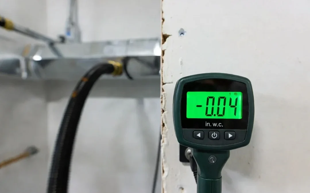
Negative pressure is not a switch you flip. It is a verifiable engineering state, a closed envelope where air is measurably moving from the surrounding space into the ductwork, and nowhere else. Guessing does not qualify. Turning on the vacuum and assuming containment is holding does not qualify either.
The operational goal is simple to state and unforgiving to execute: build a depressurized envelope, confirm it with instrumentation, and only then introduce agitation tools to the duct walls. Skip the verification step and you are not cleaning a system, you are aerosolizing contaminants into occupied space.
Contractors running air duct cleaning equipment at commercial scale treat this sequence as non-negotiable. The math and the mechanics below are what separate a controlled extraction from a liability event.
Section 1: Pre-Vacuum Engineering Calculations
Before a single collar is mounted, you need three numbers: zone volume, target air changes per hour (ACH), and required CFM to match duct cross section. Skipping any one of these means you are sizing your containment by feel.
Calculating Zone Volume
Zone volume is the cubic footage of the space you are depressurizing, whether that is a single mechanical room, a return plenum chase, or an isolated section of ceiling space.
$$V_{zone} = L \times W \times H$$
Where:
- $V_{zone}$ = Zone volume in cubic feet
- L = Interior length in feet
- W = Interior width in feet
- H = Interior height in feet
This number feeds directly into your ACH target.
Air Changes Per Hour Under Negative Draw
ACH tells you how many times the total air volume in the zone is being exchanged per hour under your vacuum draw.
$$ACH = \frac{CFM \times 60}{V_{zone}}$$
For source containment during active duct cleaning, most commercial protocols target a minimum of 4 to 6 ACH in the isolated zone. Below that threshold, contaminants disturbed by agitation tools have time to redistribute before the negative draw clears them.
Matching CFM to Duct Square Footage
This is where undersized equipment fails structurally, not just numerically. Airflow velocity, not raw suction, is what keeps debris entrained in the airstream instead of settling back into the trunk line.
$$CFM = Velocity_{FPM} \times Area_{sq ft}$$
Long horizontal trunk runs need sustained velocity, typically 2,000 to 4,000 feet per minute (FPM), to keep particulate suspended through the full run length. A 150 to 300 CFM shop-vac class unit cannot generate that velocity across a duct cross section of any meaningful size. The airflow drops off, debris settles mid-run, and you end up re-cleaning the same section twice.
This is the direct argument for high-CFM systems like our Tri-Motor configuration rated at 5,000 CFM, against the industry standard of roughly 2,000 CFM for single-motor portables. More CFM at the collar means more sustained vacuum airflow performance through longer branch runs before velocity decays below the entrainment threshold, a mechanism we break down in full in our vacuum airflow performance analysis.
Section 2: Building the Suction Plenum and Collar Installation
Once your zone volume, ACH target, and CFM requirement are confirmed, you move to physical containment.
Step-by-Step Collar Installation
- Identify the Access Point: Choose a straight run section, not a fitting or transition, to minimize turbulence at the collar seal.
- Cut the Service Opening: Cut to the exact collar diameter. Oversized cuts are the single most common source of local bypass leaks.
- Mount the Collar: Ensure full contact against the duct wall. Any gap here pulls unfiltered ambient air directly into your extraction path, which shows up immediately as a pressure drop on your gauge.
- Seal the Perimeter: Apply a gasket or mastic rated for the collar material. Tape alone is not a sealing method for this application; it is a temporary patch that degrades under sustained negative draw.
- Verify Collar Rigidity: Check by hand before connecting the hose. A collar that flexes under light pressure will fail under full CFM draw.
Every seal at this stage is a variable in your ACH equation. A loose collar does not just leak air, it lowers your effective CFM at the point of extraction, which drops your actual ACH below the calculated target even though your vacuum is running at rated output.
Section 3: Sealing Terminal Points and Branch Run Isolation
Containment fails most often not at the collar, but at the terminal points you forgot to track.
Systematic Terminal Tracking Sequence
- Map Every Register: Track every grille, diffuser, and register on the isolated branch run before starting. Work from a printed or digital duct diagram, not memory.
- Seal Terminals Progressively: Fix in a sequence, typically farthest from the collar first, working back toward the access point. This prevents you from sealing a terminal, then losing track of whether the next one downstream was already covered.
- Confirm Outdoor Air Dampers: Verify dampers are closed on any run tied to fresh air intake. An open damper here means your vacuum is pulling outdoor air instead of drawing down the target zone. Your ACH numbers will read correctly on paper while containment fails in practice.
- Check Ceiling-Space Continuity: Plenum returns and unsealed ceiling tiles are a common bypass path in commercial buildings, allowing the system to pull ceiling-space air instead of duct-contained air.
This terminal-by-terminal discipline is the same operational logic behind full hvac zone isolation strategy planning on multi-zone commercial jobs, where isolating one branch without accounting for shared plenum returns produces a negative pressure reading that looks correct but is not actually containing the target zone.
Section 4: Quantitative Verification and Real-Time Monitoring
Instrumentation
Use a digital differential manometer or a Magnehelic gauge to measure the pressure differential between the isolated zone and the surrounding occupied space. Static calculations tell you what should happen. The gauge tells you what is actually happening.
Baseline Readings Before Agitation
Acceptable baseline negative pressure for source containment during duct cleaning typically falls between negative 0.02 and negative 0.05 inches of water column (in. w.c.) relative to the surrounding space, depending on job specification and local code requirements. Readings inside this range confirm the envelope is holding under your calculated CFM draw.
Do not start agitation tools until the gauge confirms this range. A reading at or near zero means your containment has a bypass leak somewhere in the collar seal or an unsealed terminal, regardless of what your CFM and ACH math predicted.
Continuous Monitoring During the Job
- Log Intervals: Log the manometer reading at job start, at the midpoint, and at completion. Filter loading and duct debris accumulation both reduce effective CFM over the course of a job, which can drift your pressure differential outside the acceptable range mid-work.
- Re-Verify Tool Swaps: Re-verify after any tool change. Swapping agitation heads or extending hose length changes system resistance and can shift your actual draw at the collar.
- Treat Drops as Stop Conditions: Treat a mid-job pressure drop as a stop condition, not a note for later. Re-check every seal point before resuming.
Summary Checklist
| Step | Verification Method | Pass Criteria |
| Zone Volume & ACH | Manual measurement and formula calculation | Minimum 4 to 6 ACH achieved |
| CFM to Duct Match | Fluid dynamics velocity calculation | 2,000 to 4,000 FPM sustained airflow |
| Collar Seal | Visual and hand-pressure rigidity check | No visible gap, rigid under full load |
| Terminal Points | Sequential mapping and poly-tape sealing | All grilles, diffusers, registers blocked |
| Pressure Verification | Digital manometer or Magnehelic gauge | Negative 0.02 to negative 0.05 in. w.c. |
Containment is not assumed. It is measured, logged, and reconfirmed before agitation tools ever touch the duct wall.