
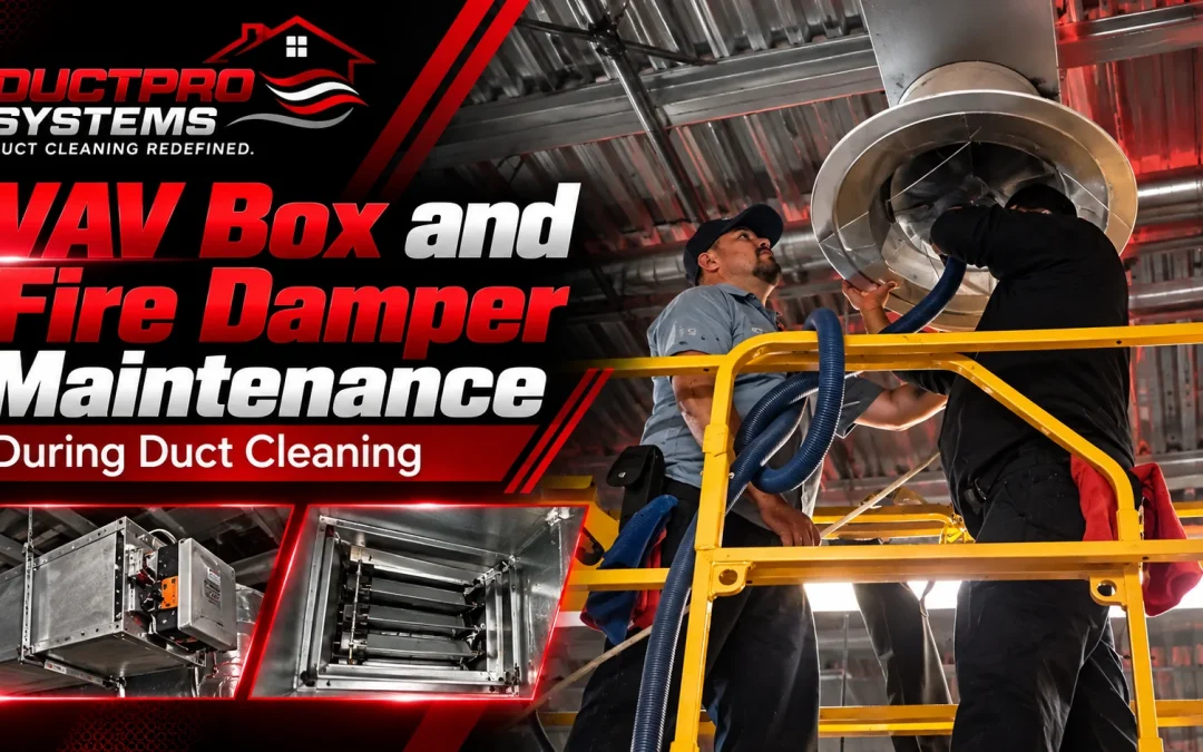
Commercial duct cleaning involves more than removing accumulated debris from sheet-metal surfaces. VAV boxes, flow-sensing arrays, fire dampers, smoke dampers, actuators, pneumatic control lines, and other terminal components can be located directly within or adjacent to the duct sections being cleaned.
These components can affect airflow control, pressure measurement, damper operation, and building automation functions. The cleaning process therefore has to account for internal hardware before agitation and extraction begin.
The objective is not simply to create airflow through the duct. It is to establish a controlled extraction path while preventing tools, debris, pressure changes, or accidental component movement from disturbing equipment that the HVAC system depends on.
This is particularly important on commercial systems where individual zones may be controlled through VAV terminals and where fire or smoke dampers form part of the building’s life-safety system. Component protection should be coordinated with the equipment manufacturer, building facilities team, BAS operator, and applicable site requirements.
VAV Terminals: Protecting Flow-Sensing Arrays
A VAV box is both an airflow-control device and a measurement point within the HVAC system. Many VAV terminals use an averaging or multi-point pressure-sensing array near the inlet. The array measures pressure conditions across the incoming airstream, allowing the controller to determine airflow and modulate the terminal damper.
The exact sensor arrangement varies by VAV manufacturer and model, so technicians should identify the installed configuration before introducing agitation equipment into the adjacent duct section.
Averaging Pitot Array Configurations
Commercial VAV terminals can use different flow-sensing geometries. Some use cross-shaped or multi-port averaging arrays positioned across the inlet. Others use multi-point arrangements designed to sample different portions of the incoming airflow.
The basic relationship between differential pressure and airflow can be represented as:
Q=K×A×2ΔPρQ = K \times A \times \sqrt{\frac{2\Delta P}{\rho}}
Where:
- Q is volumetric airflow
- K represents the flow coefficient associated with the sensing and terminal configuration
- A is the relevant flow area
- P is the measured differential pressure
- is air density
The flow coefficient, sensor arrangement, controller programming, and calibration method are manufacturer-specific. A cleaning contractor should therefore use the installed VAV documentation when determining whether a sensor requires verification or recalibration.
Protecting the Sensing Assembly During Agitation
The pressure-sensing tubes connecting the sensing ports to the transducer can be vulnerable to mechanical contact. A brush, whip, or other agitation tool can bend, dislodge, or otherwise disturb tubing or sensor connections if it contacts the assembly.
A practical protection sequence includes:
- Identify the VAV box and its inlet before cleaning the adjacent duct segment.
- Determine the location of the flow-sensing array and associated tubing where accessible.
- Establish an appropriate exclusion area around sensitive components before agitation begins.
- Keep rotary brushes and other aggressive mechanical tools away from exposed sensing hardware.
- Direct agitation toward the duct surface rather than directly toward the VAV sensing assembly.
- Protect exposed components when the manufacturer’s instructions permit temporary covering or isolation.
- Remove temporary protection before final extraction and return to service.
- Verify that accessible sensing tubes, connections, and components have not been displaced or damaged.
The appropriate exclusion distance depends on the component configuration, cleaning method, tool, access arrangement, and manufacturer’s instructions. It should not be treated as a universal dimensional requirement.
The same principle applies when using professional air duct cleaning equipment. Extraction power and agitation capability have to be controlled in relation to the component being protected rather than applied indiscriminately throughout the system.
Fire and Smoke Damper Assemblies
Fire dampers and smoke dampers require a different level of procedural control because they perform functions associated with fire and smoke containment.
A commercial HVAC system may contain fire dampers, smoke dampers, or combination fire-smoke dampers. Their construction and operating mechanisms vary. Some assemblies use fusible links or other heat-responsive components, while smoke-control assemblies may use electrical actuators and building automation or life-safety control interfaces.
The exact procedure for cleaning around a damper should be based on the installed assembly, manufacturer instructions, building procedures, and applicable requirements. A generic cleaning procedure should not override those requirements.
Fusible-Link Fire Dampers
Where a fire damper uses a fusible link, the link and its retaining hardware should be identified before agitation begins.
The technician should inspect the accessible assembly for obvious conditions such as corrosion, physical damage, displacement, or loose hardware. If the damper or its release mechanism appears compromised, cleaning should not proceed as though the component were in normal condition. The condition should be brought to the attention of the responsible building or HVAC personnel.
During cleaning:
- Confirm the damper’s condition and position before beginning work in the adjacent duct segment.
- Identify the fusible link and retaining mechanism.
- Prevent agitation tools from striking the link, retaining hardware, or damper blades.
- Avoid directing concentrated air or mechanical agitation directly at the assembly.
- After cleaning, visually inspect accessible components for displacement or damage.
- If operational testing or resetting is required, follow the damper manufacturer’s procedure and the building’s established maintenance requirements.
A cleaning-triggered damper cycle should not automatically be treated as a substitute for a required inspection or testing procedure. Documentation and testing requirements can vary according to the building, installed equipment, applicable requirements, and AHJ.
Smoke Dampers and Combination Fire-Smoke Dampers
Smoke dampers commonly incorporate motorized actuators and may be connected to the building’s fire alarm, smoke-control, or BAS infrastructure.
The actuator should be identified before cleaning begins, particularly when the duct segment will be exposed to agitation or when access is close to the damper assembly.
Do not assume that every actuator has the same hold-open mechanism, control sequence, fail position, or electrical interface. Some procedures require coordination with facilities personnel or the BAS operator before the damper is isolated.
A suitable workflow is:
- Identify the damper, actuator, and associated control interface.
- Determine the manufacturer’s required procedure for placing the assembly in the appropriate maintenance condition.
- Coordinate any required isolation with the responsible building personnel.
- Keep agitation tools and uncontrolled airflow away from the actuator and damper blades.
- Restore the control system according to the approved procedure after cleaning.
- Verify the damper’s commanded operation where the responsible personnel and system configuration require it.
- Document any operational check performed.
This approach treats a life-safety damper as a controlled system component rather than simply another section of ductwork.
Actuator and Control-Loop Isolation
VAV boxes and terminal dampers may use electronic actuators connected to a DDC controller or BAS. Other systems may use different control arrangements.
The actuator itself can be protected from direct impact, while associated wiring, terminal connections, feedback devices, and control enclosures also require consideration.
During agitation, loose debris can enter exposed enclosures, and tools can catch or pull control wiring. The risk depends on the physical installation, enclosure condition, cleaning method, and accessibility.
A practical isolation sequence is:
- Identify the actuator and associated control wiring before agitation.
- Determine whether the actuator or control circuit needs to be isolated according to the equipment and building procedure.
- Protect exposed control connections from direct debris impact where appropriate.
- Keep agitation equipment clear of exposed wiring and actuator components.
- Inspect accessible connections after extraction.
- Restore the control system according to the approved building procedure.
- Confirm normal actuator response before returning the affected zone to normal operation.
Control voltage, wire type, feedback method, actuator torque, and other characteristics vary among manufacturers and equipment generations. Those specifications should come from the installed equipment documentation.
Where BAS control is involved, coordination can be as important as the cleaning equipment. The cleaning crew should know which components are being isolated and who is responsible for returning them to normal service.
Pneumatic Control Lines
Older commercial HVAC systems may use pneumatic controls rather than modern DDC controls. These systems can contain small pneumatic lines routed along or near duct surfaces.
The lines can be vulnerable to physical contact from agitation equipment. A tool that catches a line, pulls it against a bracket, or otherwise disturbs the tubing can create a problem that may not be immediately apparent.
Before cleaning a segment containing pneumatic controls:
- Identify visible pneumatic tubing and its routing.
- Determine which lines serve the components in the working section.
- Keep agitation tools away from exposed tubing.
- Protect vulnerable sections where appropriate for the installation.
- Inspect the tubing and connections after extraction.
- Report visible damage or questionable connections rather than assuming the control loop remains functional.
The material, diameter, operating pressure, attachment method, and routing of pneumatic lines vary by installation. Those details should be established from the installed system rather than assumed from a general commercial HVAC specification.
Controlled Extraction and Pressure Management
Component protection is closely connected to extraction control.
A vacuum connected to a duct system creates a pressure differential that establishes airflow toward the collection equipment. The actual pressure produced at a particular component depends on the complete airflow path, including duct geometry, leakage, restrictions, access openings, dampers, hose configuration, and the operating characteristics of the extraction equipment.
For that reason, a generic statement that a particular extraction airflow will always produce a specific static pressure across a damper is not reliable.
A high-capacity extraction system can create significant pressure effects when a duct segment becomes excessively restricted or effectively sealed. The appropriate response is controlled isolation and monitoring, with the extraction equipment operated within its published specifications.
For additional discussion of the relationship between airflow, pressure, hose restrictions, and extraction-system resistance, see DuctPro’s HVAC static pressure analysis guide.
The DuctPro Tri-Motor Vacuum
DuctPro’s current published Tri-Motor Vacuum specifications are:
| Specification | Published value |
| Airflow | 330 CFM |
| Air Watts | 900 Air Watts |
| Water Lift | 220 inches |
| Motor configuration | Three independent vacuum motors |
| Debris capacity | 12 gallons |
| Operating voltage | 120 Volts |
These specifications describe the DuctPro Tri-Motor system. They are not universal airflow or pressure requirements for commercial duct cleaning.
The DuctPro Tri-Motor Vacuum System should be operated within its published specifications. Equipment selection and operating conditions should be matched to the specific HVAC system, access arrangement, cleaning method, and working section.
Avoiding Uncontrolled Pressure Loading
A damper blade should not become an unintended pressure-control device.
If a working segment is isolated too aggressively, the extraction path can become restricted. If another damper, terminal, or component is left in an unexpected position, the resulting pressure distribution may differ substantially from the technician’s intended airflow path.
Before extraction:
- Identify the boundaries of the working segment.
- Identify dampers and terminal devices within or adjacent to that segment.
- Confirm which components are intended to remain open, closed, or isolated.
- Establish a clear airflow path toward the collection equipment.
- Start extraction under controlled conditions.
- Observe the system for unexpected restriction, component movement, or abnormal operating behavior.
- Adjust the isolation arrangement if the intended airflow path cannot be maintained.
The objective is controlled negative pressure and debris transport, not maximum airflow at any cost.
Segment Isolation
Commercial systems are best approached as a series of manageable working sections rather than as one unrestricted duct network.
Segment isolation concentrates the available extraction airflow through the section being cleaned. It can also make component protection easier because the technician can identify the specific dampers, VAV terminals, access points, and control components affected by each cleaning stage.
A typical sequence is:
- Select the working segment.
- Identify all terminal and control components associated with it.
- Establish the extraction connection.
- Isolate non-working portions as appropriate for the system design.
- Confirm that the intended airflow path remains available.
- Introduce agitation progressively.
- Observe component behavior while extraction continues.
- Complete the segment before moving to the next section.
The exact isolation method depends on the duct layout. A multi-zone system may require a different arrangement from a simple single-branch system. Dampers that are part of the building’s normal control sequence should not be manually repositioned without understanding their function and coordinating with the responsible personnel.
The principle is straightforward: isolate enough of the system to create an effective extraction path while avoiding unnecessary pressure loading on sensitive components.
Post-Cleaning Verification
Extraction is not the final step when the cleaned section contains VAV terminals, dampers, actuators, or other control components.
The technician should verify that protected components remain in their intended condition before the system is returned to normal operation.
VAV Verification and Recalibration
Where a VAV terminal was exposed to cleaning activity, check the accessible sensing components, tubing, connections, and actuator for obvious displacement or damage.
If the cleaning procedure required isolation or if the building’s commissioning procedure calls for airflow verification, the appropriate BAS or test-and-balance procedure should be followed.
Recalibration should not be performed automatically simply because duct cleaning occurred. Whether recalibration is necessary depends on the condition of the VAV system, the manufacturer’s instructions, the building’s control sequence, and the results of verification.
Where formal airflow verification is required, readings can be compared with the system’s established design or TAB documentation. Any adjustment should use the installed controller’s documented calibration procedure rather than an assumed universal tolerance.
Fire and Smoke Damper Verification
Any damper that was manually operated, isolated, or otherwise affected by the cleaning procedure should be returned to its required operating condition according to the manufacturer’s and building’s procedures.
The verification record can include:
- Damper identification or location
- Pre-cleaning condition
- Whether the damper was operated or isolated
- Post-cleaning condition
- Any abnormal condition observed
- Person responsible for the verification
- Date of the check
This documentation provides a useful record of what happened to the component during the cleaning project. It should not be represented as satisfying a particular fire-life-safety inspection requirement unless that requirement has been established for the building.
Actuator Verification
For electronic actuators that were isolated during cleaning, restore the control system using the approved procedure and confirm that the actuator responds normally.
Where the system provides position feedback, that feedback can be checked by the responsible technician or controls personnel. If the actuator does not respond as expected, the condition should be investigated before the zone is returned to normal operation.
Documentation and Return-to-Service Checks
Good documentation establishes what was changed during the cleaning process and what was verified afterward.
For commercial projects, the closeout record can include:
- Working segments cleaned
- Access points used
- VAV boxes or terminal units encountered
- Fire and smoke dampers encountered
- Components requiring temporary isolation
- Control components affected by the cleaning process
- Visible damage or pre-existing defects
- Post-cleaning component condition
- Operational checks performed
- Items requiring follow-up by HVAC, controls, or life-safety personnel
This information also helps distinguish pre-existing component problems from conditions discovered after cleaning.
The return-to-service sequence should be coordinated with the building’s normal operating procedures. VAV terminals, dampers, actuators, and BAS points should be restored to their intended state before the affected system is returned to normal operation.
For a broader overview of commercial cleaning workflow, including assessment, sectioning, access, extraction, and verification, see DuctPro’s commercial air duct cleaning process guide.
Practical Guidance for Protecting Internal HVAC Hardware
The most reliable approach to component protection is to treat the duct system as an integrated mechanical and control system rather than as an empty passage for debris removal.
Before extraction begins, identify the internal hardware. Determine which components can be affected by agitation, airflow, pressure changes, or temporary isolation. Establish the working segment and extraction path. Coordinate with building personnel when BAS, pneumatic controls, or life-safety equipment are involved.
During cleaning, keep mechanical agitation away from sensitive components and avoid creating an uncontrolled pressure condition. Use the extraction equipment within its published specifications and adapt the procedure to the HVAC system being serviced.
After cleaning, inspect the components exposed to the work. Restore controls and dampers according to the applicable procedures. Where airflow verification, recalibration, or life-safety testing is required, use the appropriate manufacturer, building, TAB, controls, or AHJ procedure rather than substituting a generic cleaning checklist.
Duct cleaning equipment is only one part of the process. Effective commercial extraction depends on matching the equipment, airflow path, agitation method, component protection, segment isolation, and verification procedure to the HVAC system being serviced.
For DuctPro Systems, equipment specifications should always be considered alongside the requirements of the HVAC system being serviced. The Tri-Motor Vacuum should be operated within its published specifications, with the cleaning method and airflow path adapted to the specific system and working section.
The goal is not simply to remove debris. It is to complete the extraction while preserving the airflow-control, damper, sensing, and life-safety components that keep the commercial HVAC system operating as designed.