
A vacuum system’s rated airflow does not necessarily equal the airflow available at the duct opening. Hose length, diameter, bends, connections, leakage, filters, and duct resistance can all affect the operating condition of the complete extraction path.
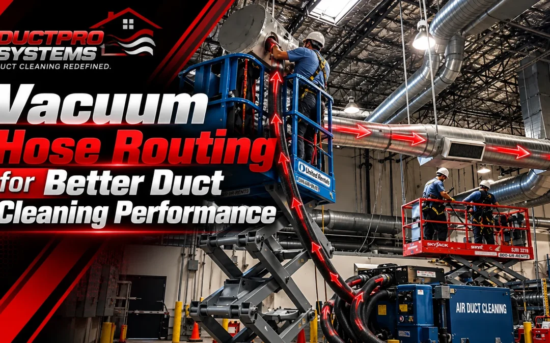
Hose routing is often treated as a simple logistics task: get the hose from the vacuum unit to the duct opening by whatever path is convenient. In practice, the routing path affects the resistance of the extraction system. Hose length, bends, couplings, fittings, and leakage can all influence the airflow and pressure available at the working end. Understanding these factors helps contractors plan an extraction path that preserves as much usable performance as practical.
This is one reason professional air duct cleaning equipment should be considered as part of a complete airflow system rather than evaluated only by motor power. A vacuum source’s performance at the working end depends partly on the path connecting the machine to the duct.
Why Hose Routing Determines System Performance
Airflow through a hose behaves according to the same principles that govern airflow through the duct system itself. Static pressure, resistance, and velocity are related, and any change in one affects the others. The vacuum unit generates a pressure differential. The hose is the conduit through which that differential does its work. If the hose introduces excessive resistance, the pressure differential is consumed overcoming that resistance rather than generating transport velocity at the working end.
This matters because duct cleaning is not primarily a suction exercise. It is a transport exercise. Dislodged debris has to be entrained in an airstream and carried the full distance to the collection system. If velocity drops below the threshold needed to keep particles suspended, debris settles inside the hose itself, inside the ductwork, or both. A vacuum gauge reading strong static pressure at the machine tells a contractor almost nothing about what is happening at the far end of a poorly routed hose run.
Pressure Loss Through Hose Length
Every length of hose adds frictional resistance. Air moving through a hose interacts with the interior wall surface, and that interaction consumes energy. The longer the hose run, the more cumulative pressure loss occurs before the airstream reaches the duct opening.
Pressure loss through a hose depends on more than length alone. It is also affected by airflow rate, hose diameter, interior surface, bends, fittings, and the characteristics of the complete extraction path. As airflow increases, friction-related losses can increase substantially. This is why adding a long hose run to reach a distant duct opening can reduce the performance available at the working end, particularly when the routing also includes multiple bends or restrictive connections.
Practical implication: minimize hose length wherever the site allows it. Positioning the vacuum unit closer to the work, even if that means repositioning between rooms or floors, often preserves more usable transport velocity than running a single long hose from one fixed location.
Hose Diameter and Airflow Capacity
Diameter governs how much air a given hose can carry at a given velocity. A narrower hose increases velocity for the same airflow volume but also increases resistance and pressure loss. A wider hose reduces resistance but can drop velocity below the point needed for particle transport if the vacuum source cannot maintain sufficient CFM through the larger cross-section.
This is a genuine engineering trade-off, not a simple “bigger is better” decision. The correct diameter depends on the CFM the vacuum source can sustain and the transport velocity required for the debris being removed. Fine dust requires less velocity to stay entrained than heavier construction debris or rodent nesting material. Matching hose diameter to the vacuum system’s realistic delivered airflow, the hose configuration, and the material being transported is an important part of planning the extraction path before the job begins.
Understanding the relationship between rated CFM and delivered airflow, covered in CFM Required for Professional Duct Cleaning, is foundational here. A machine’s rated capacity assumes ideal conditions. Real hose runs never are ideal.
Friction Loss and Turbulence
Friction loss occurs at the boundary layer where moving air contacts the hose interior. Turbulence occurs when airflow disrupts from smooth, layered movement into chaotic, mixed movement. Both consume energy that would otherwise contribute to transport velocity at the working end of the hose.
Turbulence increases sharply at transition points: couplings, reducers, sharp bends, and any location where hose diameter or direction changes abruptly. A smooth, consistent hose run with minimal transitions generally creates a more predictable airflow path and avoids unnecessary resistance caused by abrupt changes in direction or geometry.
Corrugated hose interiors, common in flexible vacuum hose construction, introduce a baseline level of friction loss that smooth-wall hose does not. Contractors working with corrugated hose should account for the additional resistance associated with its interior surface when evaluating the expected performance of the complete hose run.
Bend Radius and Airflow Restriction
A bend in a hose does more than change direction. The bend geometry can increase resistance and create additional turbulence as the airstream changes direction. The effect depends on factors such as hose diameter, bend radius, airflow, and the geometry of the connection.
In general, tighter bends introduce more resistance than gradual curves. A sharp ninety-degree bend with a small radius can create substantially more resistance than a gradual curve, although the actual effect depends on the hose diameter, bend radius, airflow, and fitting geometry. Avoiding unnecessary sharp turns is therefore a practical way to reduce resistance in the extraction path.
Sharp Turns Versus Gradual Curves
Gradual curves distribute the directional change over a longer section of hose, allowing the airstream to adjust progressively rather than abruptly. This preserves more of the velocity profile than a sharp turn, where the airstream is forced to redirect almost instantaneously.
In practice, this means routing hose around obstacles with sweeping curves rather than tight angles whenever the site allows it. It also means avoiding routing choices that force a hose to double back on itself or thread through a series of close-together direction changes, since the cumulative effect of several moderate bends can exceed the restriction of one sharp bend.
Hose Elevation Changes and Field Considerations
Vertical hose runs can introduce additional operating challenges, particularly when the extracted material includes heavier debris or moisture. The effect depends on the material being transported, airflow conditions, hose configuration, and the complete extraction path. These factors become more relevant when routing hose through stairwells, vertical shafts, multi-story mechanical rooms, or between floors.
When routing through areas with significant elevation changes, contractors should consider the complete route rather than treating elevation as simply another measure of hose length. Keep the route as direct as practical, avoid unnecessary transitions, and verify that the extraction system continues to perform as intended under the actual job conditions.
Hose Routing for Residential Versus Commercial Projects
Residential routing typically deals with shorter runs, more turns due to confined interior spaces, and easier repositioning of the vacuum unit between rooms. The primary engineering challenge is often bend management rather than raw distance.
Commercial routing introduces different challenges. Duct runs in commercial buildings can require longer hose lengths to reach interior duct sections, plenum spaces, or rooftop units, while the vacuum unit may be more difficult to reposition because of access constraints, power requirements, or building logistics. On these jobs, hose length, diameter, bends, and connection quality become important considerations because each can affect the performance available at the working end. The DuctPro Tri-Motor Vacuum System uses three independent vacuum motors and is designed for professional duct-cleaning applications. Its published specifications should be considered together with the hose configuration, duct layout, access arrangement, and operating conditions of the specific job.
Hose Placement Relative to the Vacuum Unit
The angle and position at which hose connects to the vacuum unit inlet affects performance before the airstream has traveled a single foot of the run itself. An inlet connection that forces an immediate sharp bend at the machine reduces effective intake efficiency from the first moment of operation, regardless of how well the rest of the run is routed.
Positioning the vacuum unit so the primary hose run leaves the inlet with a smooth, direct path can reduce unnecessary resistance at the beginning of the extraction run and make the overall hose configuration easier to manage.
Managing Multiple Hose Sections and Connections
Every coupling between hose sections is a potential source of both turbulence and leakage. Couplings can introduce changes in internal geometry and, when poorly aligned or restrictive, can add resistance to the airflow path. Leakage occurs when couplings are not fully seated or when seals degrade with repeated field use.
Contractors should minimize the total number of couplings in a run wherever practical, favoring fewer, longer hose sections over multiple shorter sections joined together. When multiple sections are unavoidable, verifying that each coupling is fully seated and free of visible wear becomes part of the pre-extraction check, not an afterthought performed only if performance seems low.
Air Leakage at Couplings and Fittings
Leakage at a coupling can reduce the amount of airflow reaching the intended extraction point and alter the pressure conditions along the hose run. Air entering the system at a leak point reduces the pressure differential available to move air, and consequently debris, from the intended extraction point. A hose run can appear intact while leaking enough air at its connections to meaningfully reduce transport velocity at the working end.
This is a common, underdiagnosed cause of inconsistent extraction results on jobs where the vacuum unit itself is functioning correctly. A methodical check of every coupling under load, not just visually before the job starts, catches leakage that would otherwise be misattributed to motor performance or duct condition.
Hose Routing and Transport Velocity
Transport velocity is a key factor in determining whether debris remains entrained in the airstream or settles inside the system. Every factor discussed so far, length, diameter, bends, elevation, couplings, ultimately expresses itself as a change in transport velocity somewhere along the hose run.
A hose run designed to minimize unnecessary resistance can preserve more of the vacuum system’s available airflow and pressure at the point where the hose connects to the duct being cleaned. Understanding Vacuum Suction Power in isolation from hose routing gives an incomplete picture, since delivered performance at the duct opening is a function of both.
Hose Routing During Negative Pressure Extraction
Negative pressure extraction depends on maintaining a controlled pressure differential across the section of duct being cleaned. Hose routing affects this directly, because pressure loss through a poorly routed hose reduces the negative pressure actually available at the duct opening, even if the vacuum unit itself is generating full rated output.
Contractors establishing negative pressure for a section of ductwork should consider hose routing losses when evaluating the pressure conditions at the work area rather than assuming that the vacuum unit’s published output will be reproduced unchanged at the duct opening.
Relationship Between Hose Routing and Zone Isolation
Zone isolation controls where air is permitted to move within the duct system during cleaning. Hose routing interacts with zone isolation in a way that is easy to overlook: if the hose run introduces substantial resistance, the pressure conditions available at more distant sections of an isolated zone may differ from those expected at the vacuum unit, even when the isolation arrangement itself is correct.
This is why hose routing decisions should be made in coordination with HVAC Zone Isolation Strategy During Professional Duct Cleaning rather than treated as a separate, purely mechanical concern. A well-isolated zone with a poorly routed hose can still underperform.
Common Contractor Mistakes
The most frequent routing errors share a common root cause: optimizing for convenience at the point of connection rather than for airflow performance across the full run.
Running hose through the shortest visible path rather than the path with the fewest and gentlest bends is a common one. So is stacking multiple hose sections together for reach rather than repositioning the vacuum unit closer to the work. Leaving couplings loosely seated because the run “looks connected” is another, along with ignoring elevation transitions when routing through multi-story spaces, and assuming a machine’s rated CFM will be delivered regardless of how the hose is arranged.
These factors are not captured fully by a vacuum’s headline specification. Their effects become apparent only when the equipment is connected to the actual hose and duct configuration used on the job.
Practical Engineering Recommendations
Route hose with as few unnecessary bends as the site allows, favoring gradual curves over sharp turns wherever practical. Position the vacuum unit close enough to the work to avoid unnecessarily long hose runs, particularly on commercial jobs where access can make repositioning difficult. Minimize unnecessary couplings and verify that each connection is properly seated and free of visible damage or leakage. Consider elevation changes as part of the complete hose configuration rather than simply adding them to total hose length. Match hose diameter to the vacuum system, hose configuration, and material being transported, and evaluate actual job conditions rather than relying solely on the vacuum’s rated CFM. On commercial work, consider hose routing when planning negative pressure and zone isolation so that the intended extraction path can be maintained.
Hose routing is not a logistics task performed after the engineering decisions have been made. It is one of the engineering decisions. Contractors who treat hose routing as part of the extraction design can reduce avoidable resistance and make better use of the performance available from the equipment between the vacuum unit and the duct.
This systems-level approach helps contractors use professional air duct cleaning equipment more effectively by considering the vacuum, hose configuration, duct system, and extraction conditions as one connected airflow path.