

A duct system with a 15% leakage rate is not 15% less efficient. It is functionally broken for extraction purposes. A meticulous duct leakage inspection exists because a leaky trunk line does not behave like a slightly weaker version of a sealed one. It behaves like a perforated straw. Suction finds the shortest path to ambient interstitial air instead of pulling along the duct wall where debris actually sits, and the agitation crew ends up dislodging material that never leaves the system.
This distinction matters because most contractors still frame leakage testing as an energy conservation metric—something an HVAC engineer checks for utility savings. In a remediation context, it is a containment metric. If you cannot verify where air is entering and exiting the envelope, you cannot verify that debris is actually being transported to the collection unit rather than redistributed into occupied space.
Crews running air duct cleaning equipment at scale treat pre-extraction leakage diagnostics as a gate, not a formality. Turning on a high-CFM vacuum against an unverified envelope means you are guessing at containment, and guessing is how callbacks get generated.
Section 1: The Aerodynamic Toll of Structural Leakage
Why Leakage Percentage Is Not a Linear Efficiency Loss
Static suction at the vacuum collar is generated against total system resistance. Every unsealed joint, seam, or disconnected boot is a parallel air path with lower resistance than the intended duct run. Air takes the path of least resistance, and a structural leak is almost always lower resistance than a long branch run terminating at a far register.
The result is a massive, disproportionate velocity penalty. A system with a 15% leakage rate does not lose 15% of its transport capacity. Field data across commercial remediation jobs consistently shows leakage in this range producing a 35% to 40% drop in particulate transport velocity at the far end of the affected branch.
The Mechanics Behind the Velocity Disproportion
Transport velocity inside the system is governed directly by the fluid continuity relationship:
$$V = \frac{Q}{A}$$
Where:
- V = Velocity in feet per minute (FPM)
- Q = Volumetric flow rate in cubic feet per minute (CFM)
- A = Duct cross-sectional area in square feet
The structural leakage penalty does not reduce volumetric flow uniformly across the full run. It reduces effective flow most severely at the terminal end of the branch. This happens because every micro-fracture upstream siphons away suction capacity before it can reach the far register. A 40-foot branch run with three unsealed transverse joints delivers dramatically less terminal velocity than a pristine run, even though total system CFM measured at your vacuum inlet reads normal.
Why Structural Deficits Produce Stagnant Debris Beds
Coarse particulate requires a sustained minimum velocity of 2,000 to 4,000 FPM to stay fully entrained in a horizontal sheet metal airflow column. Drop below that threshold mid-run, and debris does not slow down gradually; it settles immediately.
A branch line that reads acceptable CFM at the collector but has a structural failure at its midpoint will show a stagnant debris bed exactly where velocity crossed below the entrainment threshold. This is the ultimate argument for running a dedicated leakage scan before starting extraction.
Section 2: Advanced Diagnostic Methodologies
Structural leakage does not announce itself. It must be uncovered using physical instrumentation rather than field inferences.
Pressure Pan Testing Across Registers
- Seal System Framework: Seal the system completely at the primary air handler and at all registers except the single terminal under test using temporary mastic-backed covers.
- Mount the Pan Enclosure: Mount the pressure pan cleanly over the isolated register, connecting its output port to a calibrated digital manometer.
- Establish Reference Draw: Activate your test fan to establish a stable reference pressure differential.
- Analyze Pan Pressure Outliers: Read the pan pressure. A tight, well-sealed branch will register a high pressure value close to the system reference. A branch with structural leakage will register a markedly lower value because leaked air is bypassing the register entirely. Repeat this across all registers to find your compromised branches.
Localized Theater Fog Injection with Thermal Camera Tracking
- Positive Pressure Injection: Inject non-toxic theater fog at the main service collar under mild positive pressure.
- Track Visual Escape: Track fog egress visually at suspected joints, seams, and boot connections along the exposed run.
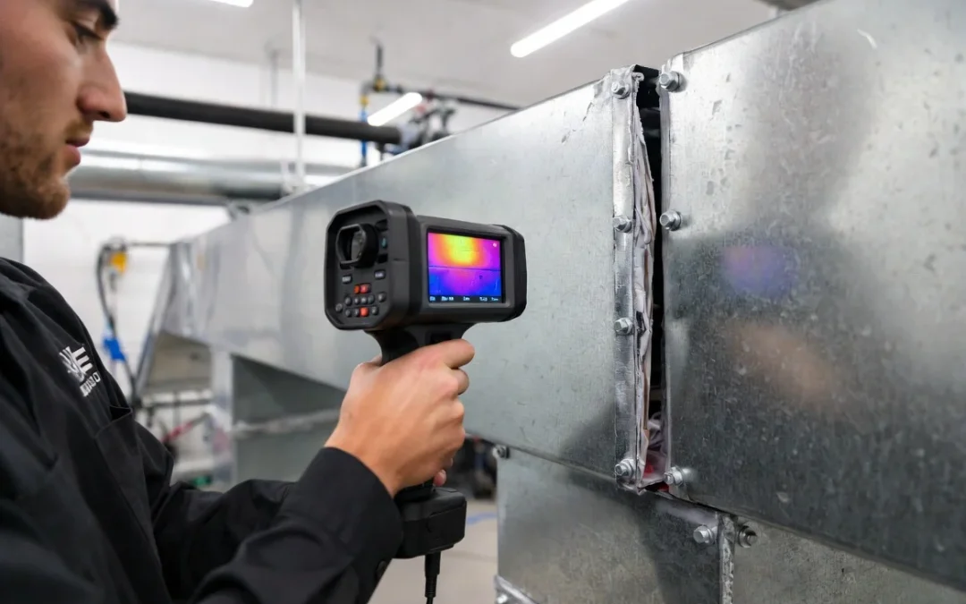
- Thermal Camera Cross-Reference: Cross-reference difficult lines with a high-resolution thermal imaging camera. Air escaping a structural fracture creates a localized temperature differential against the surrounding framing that an infrared camera picks up instantly, even when the fog dispersion is hidden behind architectural barriers. Mark every confirmed egress point directly on your mechanical blueprint.
Static Pressure Drop Comparisons
- Take AHU Baseline: Take a baseline static pressure reading at the air handler with the system in normal operation.
- Measure Terminal Points: Take a second reading at the furthest register on the branch under test.
- Calculate Friction Deviations: Calculate the total drop and compare it against the expected friction loss tables for that specific duct length and fitting count. Flag any branch where the measured drop exceeds the calculated friction tolerance by more than 10%. That excess drop is confirmed leakage, not layout friction.
Section 3: Pinpointing Micro-Fractures in the Plenum Envelope
Once advanced diagnostics confirm a specific branch is leaking, the physical failure point almost always sits within one of four categories:
- Unsealed Transverse Joints: These joints, which butt duct sections together perpendicular to airflow, are the single most common failure point. Original mastic or gasket material degrades over time due to repeated seasonal thermal expansion cycles.
- Longitudinal Seams: These seams run parallel to the airflow along the duct length. While they fail less frequently than transverse joints, they leak more severely because the seam fracture runs continuously. A longitudinal leak often shows up as a long, faint thermal trail rather than a single escape point.
- Disconnected Boot Collars: Boot collars connecting branch ducts to floor or ceiling registers are highly vulnerable to physical displacement from adjacent construction work. A partial displacement of even half an inch creates a massive bypass gap.
- Failed Service Access Doors: Access panels installed for filter access or historical camera inspections are notorious leak sources because their gaskets see heavy compression cycling. A door that does not latch with visible gasket compression is a guaranteed leak point.
Section 4: Preserving Transport Velocity and Negative Control
Temporary Sealing Before Extraction Begins
Once every leak point is mapped, seal each fracture temporarily using non-destructive materials rated for immediate remediation:
- Foil-Faced Tape: Apply high-tack, HVAC-rated foil tape across transverse joints and minor longitudinal seam gaps.
- Mastic Compound: Deploy heavy mastic compound at joints with irregular gap geometry that tape cannot conform to.
- Temporary Boot Clamps: Utilize adjustable collar clamps to firmly re-seat displaced boot connections without permanent mechanical fastening.
- Gasket Strip Replacement: Swap out failed gasket strips at access doors where compression memory has been lost.
Every temporary seal applied must be logged against your duct diagram with the diagnostic method that identified it, the material used, and the technician who completed the seal. This creates a bulletproof field record.
Re-Verification Prior to Tool Introduction
Sealing is not the final step. Re-run your static pressure drop comparison or pressure pan test after sealing, before introducing a single agitation device. Confirm the measured drop now falls safely within tolerance of the calculated expected value.
This step is identical in principle to the verification discipline used when you establish negative pressure duct cleaning boundaries: the gauge confirms what your calculations predicted, and you never proceed on assumptions alone.
Why Multi-Zone Envelopes Demand Independent Scans
On commercial jobs spanning multiple floors or wings, a leak sealed in zone one has no bearing on zone three. Leakage diagnostics and temporary sealing are a strict per-zone requirement, not a one-time pre-job task. This matches the exact operational logic behind your full hvac zone isolation strategy: containment integrity is verified zone by zone, because a sealed envelope in one section tells you nothing about the structural condition of the next.
Containment is not assumed. It is measured, logged, and reconfirmed before agitation tools ever touch the duct wall.