

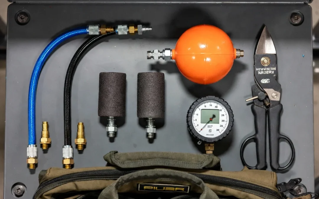
The vacuum unit is the engine. Everything else in the technician’s bag determines whether that engine produces extraction results or just moves air.
Contractors who underinvest in accessory tooling consistently get the same outcome: adequate performance on easy residential jobs, marginal performance on any system with long branch runs, flex duct transitions, or commercial trunk geometry. The vacuum’s CFM rating means nothing if the agitation tool cannot dislodge debris from the duct wall, or if a poorly seated register block is leaking 30 percent of your working static pressure before the first whip pass.
This field inventory covers every tool category that matters on a production job, from the pneumatic agitation kit to the verification instruments used at closeout. For context on how this tooling integrates with the main extraction system, the full system architecture is documented in our air duct cleaning equipment reference.
Pneumatic Agitation Tools: Moving Beyond Basic Whips
The pneumatic toolkit is where most contractors’ accessory investment is either right or wrong. The failure mode of under-tooled agitation is the same as under-CFM extraction: invisible, discovered only at post-service inspection or client callback.
Pneumatic tools require a clean, dry compressed air supply at 90 to 120 PSI working pressure. A dedicated oil-water separator on the compressor line is not optional on any job where the contractor is treating the duct system with antimicrobial agents post-extraction. Compressor oil contamination introduced via the agitation tool line will compromise the duct surface and the antimicrobial treatment.
Air Whips: Configuration by Duct Material and Diameter
The air whip is the primary agitation tool for straight trunk line sections. It operates on a rotary principle: compressed air drives a spinning head with multiple flexible skirt tails that contact duct wall surfaces as the head rotates and the tool is drawn back through the trunk.
The selection variable is tail configuration and material:
Rubber-tipped skipper tails (standard metal duct application): Designed for galvanized sheet metal trunk lines. Tail stiffness is calibrated to produce wall contact at standard 90 to 120 PSI supply without generating enough impact force to dent or deform the duct walls. Standard tail count is 6 to 8 tails per head for full circumferential coverage in trunks up to 16 inches in diameter.
Extended-reach tails (large-diameter commercial trunk application): For trunk lines above 18 inches in diameter, standard tail length does not reach the far wall of the duct from the center rotation point. Extended-reach tail configurations use 12 to 16-inch tail lengths to maintain wall contact across the full cross-section. Running a standard-tail whip in a 22-inch commercial trunk produces a cleaned cylinder in the center of the duct and an untouched debris layer around the perimeter.
Soft-durometer tails (flex duct application): Flex duct inner liner is mylar or reinforced foil over a wire helix. Standard rubber-tipped tails generate enough impact force at the flex duct corrugation peaks to abrade or perforate the liner on repeated passes. Soft-durometer tails use lower-hardness polyurethane or foam-tipped contact points that agitate the corrugation valleys without liner damage. Confirm tail type before entering any flex duct run.
Brush-head configurations (fiberglass duct board application): Duct board systems use a rigid fiberglass board interior. Rotating brush heads at reduced RPM (achieved by reducing supply pressure to 60 to 70 PSI) remove debris from the fibrous surface without abrading the glass fiber substrate. Standard rubber tails in fiberglass duct board generate surface damage that releases glass fiber into the airstream and creates a post-cleaning IAQ problem worse than the debris that was removed.
Forward-Skipper Balls: Branch Run Penetration
The forward-skipper ball is the primary agitation tool for branch run penetration. Unlike the air whip, which is drawn back through the duct as it agitates, the skipper ball uses a Venturi-effect jet that propels the tool forward through the branch run, navigating elbows and transitions without requiring direct manual positioning.
Working principle: compressed air enters the ball body and is directed through a forward-facing nozzle. The jet reaction propels the ball forward. Secondary ports vent air radially as the ball moves, generating wall-contact agitation as it travels. The technician manages tool progression via the feed hose at the access point.
Selection variables for skipper balls:
Tool diameter must match branch duct size. The standard range covers 4-inch through 10-inch branch configurations. Using an undersized skipper ball in a 10-inch branch produces center-line agitation with no wall contact on the outer 3 inches of the duct circumference. Using an oversized ball in a 6-inch branch generates sufficient friction to stall tool progression, which requires the technician to reverse air supply to retrieve the stuck tool.
Elbow navigation: Standard single-port skipper balls navigate 90-degree elbows in round duct reliably. Rectangular-to-round transitions and square-throat elbows require a flexible nose skipper configuration that compresses through the transition without jamming at the throat.
Rotating Brush Attachments: Drain Pan and Coil Access
The rotating brush on a flexible drive shaft is used for surfaces the air whip and skipper ball cannot reach: condensate drain pans, coil faces accessible through air handler access panels, and short-radius duct sections near the air handler where standard agitation tools cannot deploy at operating speed.
Brush diameter selection: match brush diameter to the surface being cleaned, not to the duct diameter. On drain pans, a 6 to 8-inch brush covers pan width efficiently. On coil faces, bristle stiffness must be selected to clean fin surfaces without deflecting or damaging the aluminum fins. A nylon-bristle rotating brush at 300 to 500 RPM is the correct specification for aluminum fin coil cleaning. Wire bristle brushes are not used on coil surfaces under any circumstances.
For deeper context on how pneumatic tools integrate with the full system extraction architecture, see our breakdown of HVAC cleaning equipment explained.
Access and Penetration Tools: Creating Professional Test Ports
Every job that requires access panel creation – meaning any commercial job and many older residential jobs where factory access points are insufficient – requires a metal penetration toolkit. The quality of the access panel cut, the frame construction, and the re-seal after extraction defines whether the contractor leaves the duct system in better mechanical condition than they found it.
Sheet Metal Nibbler
The electric or pneumatic sheet metal nibbler is the correct tool for access panel cuts in galvanized duct. The nibbler removes material in small chips, producing a clean-edged rectangular or circular cut without the distortion or sharp-edge burr that tin snips produce on longer cuts.
Operating procedure: mark the cut perimeter with a felt tip or scribe. Drill a 1/2-inch starter hole at one corner of the marked cut to provide nibbler insertion clearance. The nibbler follows the scribed line at a feed rate that maintains clean material removal without tool chatter.
Panel cut dimensions: 8 x 8 inches is the minimum access point size for deploying a standard air whip assembly. 10 x 10 inches provides more comfortable tool entry and exit and is preferred on trunks 14 inches and above. Circular cuts using a 6-inch hole saw are acceptable for skipper ball deployment in branch run access but insufficient for whip head insertion.
Aviation Snips (Compound-Lever Design)
Aviation snips are used for panel removal after the nibbler cut and for trimming the cut edges before frame installation. Compound-lever snips in left-cut, right-cut, and straight-cut configurations are required: the cut direction relative to the trunk corner determines which snip geometry produces a clean result without panel distortion.
Standard straight-cut snips are the only tool required for field access work on flat trunk sections. Left- and right-cut are needed for radius cuts and when working in confined mechanical spaces where the tool approach angle is constrained.
Access Panel Frame and Re-Seal Hardware
After extraction is complete, every field-cut access panel is re-sealed. The hardware required:
Sheet metal angle stock (22-gauge galvanized): Used to fabricate a simple L-bracket frame around the cut opening. The frame provides a clean surface for the panel cover to seat against and distributes the compression force of the foil tape seal evenly around the perimeter.
UL-Listed foil tape (3M 3340 or equivalent): The closure tape for access panels must be UL 181A-P or UL 181B-FX listed, which is the classification for pressure-sensitive tape used on HVAC duct systems. Standard foil tape or hardware-store duct tape is not UL-listed and does not meet NADCA ACR or SMACNA duct construction standards. A panel re-sealed with unlisted tape will fail any third-party inspection and represents a documented standards violation on a commercial job.
HVAC mastic sealant: For access panels on trunk lines in occupied plenum spaces or where the re-sealed panel must meet the same leakage class as the surrounding duct assembly, mastic sealant applied over the foil tape closure provides the secondary seal required. Application with a 1-inch chip brush over the taped perimeter. Mastic cure time: 2 to 4 hours before system pressurization.
Containment Accessories: The Hardware of Negative Pressure
Establishing and maintaining the negative pressure containment state requires physical hardware at every register and diffuser opening in the duct system. This is the accessory category that is most frequently underinvested and produces the most visible performance gap: a vacuum system running at rated CFM while 20 percent of that CFM leaks out of unblocked registers into the room rather than pulling debris toward the collection unit.
Magnetic Register Covers
Magnetic register covers attach directly to the metal face ring of a residential supply or return register without tools or fasteners. They seal the register opening while the adjacent duct zone is being agitated, directing the full system CFM through the active zone rather than allowing it to distribute across all open registers simultaneously.
Material specification: high-durometer magnetic sheet with a foam-edge gasket. The foam gasket is the functional component: a flat magnetic cover without a gasket does not produce a reliable seal on registers with surface damage, paint build-up, or non-flat face surfaces. An unsealed register cover with a visible gap defeats zone isolation as effectively as an uncovered register.
Cover sizing: magnetic covers are available in 4 x 10, 4 x 12, 6 x 10, 6 x 12, and 6 x 14-inch standard sizes covering the register face perimeter. Verify coverage on non-standard registers before the job. Oversized covers can be cut down. Undersized covers cannot be made to work.
Foam Blocking Plugs for Flex Duct Necks
Flex duct branch connections to the trunk line cannot always be sealed with magnetic covers because the diffuser neck may be round, non-metallic, or recessed into a ceiling cavity that does not provide a magnetic mating surface. Foam blocking plugs are sized to the branch duct nominal diameter and compressed slightly on insertion to form a friction seal inside the duct neck.
Standard plug sizes: 4, 6, 8, and 10-inch nominal. Compressible foam construction allows a 6-inch plug to seal branch connections from 5.5 to 6.5-inch actual inside diameter without requiring exact-size inventory for every branch configuration.
Critical operational point: foam plugs must be physically retrieved from every sealed branch before the HVAC system is returned to operation. A foam plug left in a sealed branch after job completion blocks airflow to that zone entirely. On a multi-zone commercial floor with 40 branch connections, a physical retrieval checklist against the zone isolation log is mandatory before system restart.
Inflatable Duct Bladders for Trunk Line Zone Isolation
For commercial trunk lines requiring zone isolation at the trunk level rather than at the branch register level, inflatable duct bladders create a temporary pressure seal inside the trunk at any isolation point. The bladder is introduced through an access panel and inflated with the same compressed air supply running the agitation tools.
Bladder sizing: the inflatable bladder must match the nominal duct dimension within 1 inch in each dimension to produce a reliable seal without over-pressurizing the bladder against the duct wall. An under-sized bladder in a 20-inch trunk will inflate to full pressure without achieving wall contact, providing no zone isolation function.
For the full system-level setup protocol covering how these containment accessories integrate with the vacuum connection point and pressure monitoring equipment, see our air duct cleaning equipment setup guide.
Diagnostic and Verification Tools: The Precision Inventory
The extraction phase of a duct cleaning job is complete when the instruments confirm it is complete, not when the technician estimates it is complete. On any job that requires documentation – every commercial job, every remediation job, and every residential job where the client is paying for a verified IAQ outcome – the diagnostic and verification tools are not optional accessories. They are the deliverable.
Handheld Anemometer
The anemometer measures air velocity in FPM at any point in the duct system via a probe introduced through a small test port or register opening. It is used at two stages of the job:
Pre-job flow mapping: Measuring air velocity at each register before extraction begins identifies zones where the existing HVAC system is delivering below-design airflow – indicating debris restriction, damper issues, or collapsed flex duct – and prioritizes the extraction sequence toward the most impaired zones.
Post-extraction flow verification: A post-extraction velocity reading at each register confirms that airflow has returned to design range and that no zone has been inadvertently blocked by a foam plug not retrieved or a damper accidentally closed during the job.
The target velocity at a residential supply register is typically 300 to 600 FPM depending on the design CFM for that zone. Values below 200 FPM post-extraction indicate a remaining restriction that requires investigation before job closeout.
Differential Pressure Manometer
The digital differential manometer monitors the pressure differential between the negative-pressure duct interior and the occupied room ambient during the extraction phase. This is the real-time containment verification instrument.
A calibrated digital manometer with a resolution of 0.001 inches WC is the correct specification. Analog magnehelic gauges are acceptable for basic monitoring but do not provide the data logging capability required for commercial job documentation. Digital manometers with USB data export allow the 30-minute interval pressure log to be included in the project closeout package as a continuous record rather than a manual observation log.
Borescope Camera
The borescope is the visual verification instrument for areas the technician cannot inspect directly. A 9mm or smaller diameter camera head on a 3 to 5-foot semi-rigid insertion rod provides access to trunk line sections adjacent to the access panel, behind fire damper blades, and in return air chase configurations with restricted access.
Borescope footage captured before agitation and after extraction provides the before/after visual documentation that commercial clients and remediation contracts require. A borescope with integrated LED lighting and 720p or higher resolution video output is sufficient for documentation purposes. The image data should be stored in a project folder with job date, property address, and zone identification for each clip.
Mirror-on-a-Wand and Inspection Scope
For visual inspection of trunk sections without the time investment of full borescope deployment, a telescoping inspection mirror – typically a 2-inch circular mirror on a 24 to 48-inch extension wand – provides direct-line visual access to the trunk interior from an access panel opening. It is a 30-second spot check tool, not a documentation tool.
Used to verify that obvious debris accumulation has been cleared from the trunk sections adjacent to the access panel and that no agitation tool components have been left inside the duct after tool retrieval. On every job, regardless of documentation requirements, the inspection mirror pass at each access panel is the final technician verification step before panel re-seal.
Conclusion: Why Quality Accessories Protect Your Equipment Investment
A high-CFM vacuum system operating against leaking register blocks, the wrong agitation tool for the duct material, and no post-extraction velocity verification can produce results no better than a lower-CFM system with a proper accessory setup. The machine’s capability is important, but the job outcome reflects the complete tooling package, not the vacuum specification alone.
The accessory investment on a complete professional toolkit runs $2,000 to $4,000 beyond the vacuum system cost. It is the investment that determines whether the vacuum system’s rated performance actually appears in the extraction results, the verification data, and the client’s post-service air quality reading.
The DuctPro Complete Air Duct Cleaning System includes the core agitation tooling, BioClean sanitizing equipment, and the accessory hardware required for production-level operation. The diagnostic instruments – manometer, anemometer, borescope – are the contractor’s own investment in documentation capability and the professional standard that separates a verified service from an unverified one.
Buy the right tools once. The callbacks you avoid pay for them.