

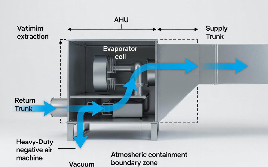
The sequencing debate inside commercial duct cleaning is not a stylistic preference. It is a fluid dynamics problem with a correct answer, and the wrong answer deposits dislodged particulate directly onto your client’s evaporator coil, blower wheel, or heat exchanger. Those are warranty claims, callback labor, and the kind of IAQ complaints that end contractor relationships.
Most technicians sequence by habit or by where the hose reaches first. Neither is an engineering rationale. The physics of your vacuum’s negative pressure gradient, the structural differences between supply and return systems, and the directional momentum of dislodged particulate all interact to produce a sequencing hierarchy. Working with that hierarchy extracts more debris per job. Working against it redistributes it.
Selecting air duct cleaning equipment that generates sufficient static pressure to overcome return-side resistance is the mechanical prerequisite that makes correct sequencing operationally viable. Without adequate vacuum capacity, sequencing protocol becomes theoretical.
Section 1: Aerodynamic Properties of Return vs. Supply Systems
Structural Differences That Govern Particulate Behavior
Supply and return trunk systems are not symmetric. They are engineered for opposite pressure regimes and opposite airflow velocities, and that asymmetry directly determines how debris accumulates, how it responds to mechanical agitation, and how much negative pressure is required to extract it.
Supply Trunk Characteristics
- Operating Pressure: Operates under positive static pressure, typically 0.5 to 2.5 inches WC above atmospheric, depending on AHU fan output and system design.
- Duct Geometry: Predominantly rectangular sheet metal or round spiral with relatively consistent cross-sections; branch takeoffs reduce trunk volume progressively from the AHU toward the terminal diffusers.
- Internal Lining: Supply trunks in commercial applications may carry 1-inch or 2-inch internal fibrous glass liner for acoustic attenuation and thermal performance; liner dramatically increases surface roughness and debris adhesion.
- Debris Profile: Fine particulate, biofilm, and oxidized metal dust accumulate in low-velocity zones near branch collars and at changes in cross-section. Coarse debris is rare in well-designed supply systems because a design velocity of 600 to 900 FPM at the trunk level keeps larger particles suspended during normal operation.
Return Trunk Characteristics
- Operating Pressure: Operates under negative static pressure, typically -0.1 to -0.8 inches WC relative to atmospheric, drawing room air toward the AHU.
- Duct Geometry: Return systems are frequently oversized relative to supply to minimize resistance and noise. In many commercial buildings, return air travels through ceiling plenums rather than dedicated sheet metal, meaning the return trunk is an open architectural cavity with no defined cross-section.
- Internal Lining: Return plenums and large-format return trunks are often unlined. Where liner exists, it faces the airstream and accumulates particulate directly on the fiber surface.
- Debris Profile: The return side carries the full spectrum of airborne particulate from occupied spaces: skin cells, textile fiber, construction dust, PM2.5, and specialized process byproducts like metal fines or chemical aerosols. Coarse debris loads on return grilles and first-segment return ductwork are substantially heavier than supply-side accumulation.
How Particulate Behaves Differently in Each System
The design velocity difference between supply and return systems changes how debris responds to agitation.
In a supply trunk operating at 700 to 900 FPM design velocity, fine particulate is distributed across the duct cross-section in a relatively uniform boundary layer. Mechanical agitation with a skipper ball or forward-pressure air whip dislodges this layer and the existing airflow assists transport toward the vacuum collection point, provided the vacuum is positioned correctly relative to airflow direction.
In a return trunk, design velocity is lower, often 400 to 600 FPM in sheet metal sections and effectively unmeasurable in open plenum returns. Coarse debris accumulates in settled beds at the duct floor. Agitation of a return trunk with a high-debris load generates a particulate cloud that does not have a reliable directional momentum.
Without aggressive negative pressure to establish a defined transport pathway, that cloud disperses throughout the accessible volume. In an open plenum return, it resettles on ceiling tile surfaces, structural members, and any unprotected HVAC components within the plenum boundary. This behavior asymmetry is why return-side cleaning demands higher vacuum capacity per unit of duct volume than supply-side cleaning of comparable length.
Section 2: Fluid Dynamics of the Negative Air Hookup
Vacuum Collar Placement and Extraction Efficiency
Where you connect the vacuum collection collar relative to the AHU is not a logistical convenience decision. It is the single variable that determines whether your negative pressure gradient assists or opposes debris transport.
The principle is continuity of flow direction. Debris in suspension travels toward the lowest pressure point in the system. Your vacuum creates that low-pressure point at the collection collar. Every foot of duct between the agitation point and the collection collar is a transport pathway, and that pathway is effective only when negative pressure is sustained continuously along its entire length without competing pressure gradients disrupting particulate momentum.
Pulling With System Design Airflow (Return Side, Vacuum at AHU Inlet)
On the return side, system design airflow moves from the occupied space inward toward the AHU. Connecting the vacuum collection collar at or near the AHU return air inlet creates a negative pressure gradient that aligns with the system’s designed transport direction. Agitation at the far end of the return trunk dislodges debris into a pressure gradient that pulls it toward the AHU and into the vacuum. This is the highest-efficiency configuration for return-side extraction.
The quantitative advantage: a 5,000 CFM vacuum positioned at the AHU return inlet, operating into an isolated return trunk of 300 linear feet with a 24 x 24 inch cross-section (4.0 sq ft), generates a transport velocity of 1,250 FPM at the collection point. Velocity at the agitation end of the trunk will be lower due to friction loss, but the gradient is continuous and directional. Debris moves toward the vacuum.
Understanding vacuum airflow performance as a function of system resistance rather than a nameplate specification is essential for calculating whether your equipment can sustain adequate transport velocity across the full length of the return run before agitation begins.
Pulling Against System Design Airflow (Supply Side, Vacuum at Terminal End)
On the supply side, system design airflow moves from the AHU outward toward the diffusers. Connecting the vacuum at the far terminal end of the supply trunk and agitating from the AHU toward the terminals pulls debris in the same direction as design airflow. This works.
Connecting the vacuum at the AHU supply outlet and agitating from the terminals back toward the AHU pulls debris against the natural momentum of supply-side particulate distribution. This is mechanically valid but requires more vacuum capacity to overcome the velocity deficit created by working against the direction of settling debris gradients. In lined supply trunks, this configuration also increases the risk of liner fiber detachment at branch collar edges, since agitation tools moving toward the AHU work against the direction the liner was installed.
The Evaporator Coil Exposure Problem
The evaporator coil and blower assembly sit between the supply and return sides of every forced-air system. This location makes them the terminal debris trap when sequencing is wrong.
If you clean the supply trunk first without sealing the AHU, agitated particulate that is not captured by the vacuum migrates back toward the AHU supply outlet. The blower wheel creates a low-pressure zone that draws this particulate directly onto the evaporator coil face. A coil that was clean before your crew arrived now carries a debris load it did not have at the start of the job.
If you then clean the return trunk with the AHU unsecured, the same phenomenon occurs from the opposite direction: a return-side particulate cloud migrates through the return inlet and deposits on the blower wheel and coil back-face. The sequencing protocol must address this exposure window explicitly.
Section 3: The Definitive Sequence Protocol
Return Trunk First: The Engineering Rationale
The correct sequence for the majority of forced-air commercial systems is return trunk first, supply trunk second. The mechanical reasoning is direct.
Return trunks carry the highest debris load by volume and particle size. Agitating a heavily loaded return system generates the largest particulate cloud of any phase of the job. If supply-side cleaning has already been completed when this cloud is generated, cross-contamination of the supply system requires debris to travel backward through the AHU: through the blower, across the coil, and into the supply plenum.
That pathway exists and is a real contamination risk, but it requires the AHU to be powered on and generating positive supply pressure during the cleaning run, which should never occur. If the AHU is locked out and tagged out per standard protocol, supply-to-return cross-contamination through the AHU is mechanically blocked during the return-side run.
Return-first sequencing means that when you transition to supply-side cleaning, the highest debris load in the system has already been extracted. Supply-side agitation dislodges a comparatively light particulate load. The contamination risk to the AHU during supply-side transition is lower.
Step-by-Step Operational Sequence
- AHU Lockout/Tagout: De-energize the air handler at the disconnect. Confirm zero voltage. Tag the disconnect. This is non-negotiable before any collection collar is connected.
- AHU Sealing: Install temporary isolation covers at both the return air inlet and supply air outlet of the AHU cabinet. Heavy-mil poly sheeting secured with foil HVAC tape provides adequate containment. The covers prevent particulate from either trunk from entering the AHU interior during cleaning runs.
- Return Trunk Zone Mapping: Identify all return branch collars, return grilles, and plenum access points within the work area. Refer to the isolation protocol in hvac zone isolation for specific device selection and seal verification procedures applicable to return-side containment.
- Return Trunk Vacuum Connection: Connect the collection collar at the return air inlet of the AHU (upstream of the AHU seal cover, not inside the cabinet). This positions the vacuum at the natural terminus of the return airflow path.
- Return Trunk Agitation: Work from the farthest return branch toward the AHU inlet. Seal each branch collar after agitation is complete before advancing to the next branch. This progressive sealing maintains transport velocity in the remaining active return volume throughout the run.
- Return Trunk Completion Verification: Borescope inspection at the main return trunk and at the two farthest branch runs from the collection point. Document debris clearance before demobilizing return-side equipment.
- AHU Interior Inspection: Remove the temporary AHU covers. Inspect the return air inlet, blower wheel, and coil back-face for any particulate that bypassed the return-side isolation. Clean as required before proceeding to the supply side.
- Supply Trunk Vacuum Connection: Connect the collection collar at the supply air outlet of the AHU. Reinstall the temporary AHU cover on the return side to prevent supply-side particulate from migrating into the now-clean return pathway during supply agitation.
- Supply Trunk Agitation: Work from the terminal branch locations back toward the AHU supply outlet, sealing each branch collar progressively as agitation is completed.
- Final AHU Inspection and Restoration: Remove all temporary covers. Inspect blower, coil face, and supply plenum. Restore all dampers, VAV overrides, and controls per the pre-job configuration log. Remove lockout/tagout and restore AHU to operational status.
When Supply-First Sequencing Is Justified
- Asymmetric Contamination: In post-construction cleanouts or systems that have had supply-side liner failure, the supply trunk may carry the dominant debris load. In this case, apply the same AHU sealing and progressive branch isolation protocol, but invert the trunk sequence. Clean the highest-load trunk first with the AHU sealed.
- Dedicated Return Fans: Large commercial systems with return air fans at the AHU create a positive pressure zone in the return duct. In these systems, the return trunk is not under negative pressure during normal operation, and the debris transport dynamics differ. Consult the mechanical drawings to confirm return fan configuration and adjust vacuum collar placement accordingly.
Section 4: Mitigating Cross-Contamination Risk During Trunk Transition
The Transition Window: Highest Risk Phase of the Job
The period between completing return-side cleaning and beginning supply-side cleaning is the highest cross-contamination risk window of the entire job. The return trunk has been agitated. Some residual particulate remains in suspension within the return volume, even after the vacuum run is complete. The AHU interior has been inspected but not yet resealed for the supply run. Any air movement through the system during this window can transport residual return-side particulate into the AHU interior or the supply plenum.
Controls for the Transition Window
- Maintain Lockout: Maintain AHU lockout throughout the transition; do not restore power for any diagnostic purpose between the return and supply runs.
- Keep Seals Active: Keep return-side branch collars sealed after agitation is complete. Do not remove foam plugs or bladders during the transition window; leave all return isolation devices in place until supply-side equipment is fully connected.
- Isolate Ports: Seal the return trunk at the AHU inlet with a temporary cover before removing the vacuum collection collar from the return connection point. The collar removal creates a brief pressure equalization event; the cover prevents this from drawing return-side air through the AHU.
Protecting the Evaporator Coil and Blower Assembly
The evaporator coil is the most expensive component in the system to remediate after contamination. A coil that requires wet chemical cleaning or physical fin straightening after a duct cleaning job represents a significant callback cost and a direct liability exposure.
Protecting it requires two layers of control:
- Physical Barrier: Heavy-mil poly isolation covers at both AHU ports, as described in the sequencing protocol. These covers handle bulk particulate.
- Pressure Differential Management: During both trunk cleaning runs, the AHU interior should be at atmospheric pressure, not under negative pressure from the vacuum. Connect the collection collar to the duct system, not to the AHU cabinet interior. If your collection collar connection point requires penetrating the AHU cabinet wall, install the collar in the duct section immediately adjacent to the AHU port, not inside the cabinet. This maintains the AHU interior as a sealed, atmospheric-pressure space rather than an active part of the vacuum circuit.
Post-Transition Verification Protocol
Before restoring the AHU to operational status, complete the following verification sequence:
- Borescope Inspection of the Supply Plenum: Confirm no visible debris accumulation at the AHU supply outlet or within the first 5 linear feet of supply trunk.
- Blower Wheel Visual Inspection: Confirm no debris deposition on wheel blades; any visible accumulation requires cleaning before power restoration.
- Coil Face Inspection: Front-face and back-face, confirming fin geometry is undamaged and no debris layer is present that would restrict airflow.
- Filter Bank Inspection: Replace or document condition of all installed filters; a clean filter reading at the end of a remediation job confirms the AHU interior was adequately protected during the cleaning runs.
- Static Pressure Baseline Test: After restoration, measure supply static pressure at the AHU outlet and compare to the pre-job baseline; a significant increase indicates a blocked branch or an unseated isolation device that was not removed during demobilization.
Document all inspection findings with photographs. The post-transition verification record is the technical evidence that the job was completed without introducing new contamination at the system core.