

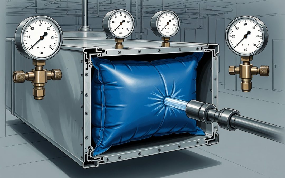
Open-loop duct cleaning is an engineering failure masquerading as a service. When a technician connects a vacuum to one point of an un-isolated system and begins agitating debris across multiple branch circuits simultaneously, dislodged particulate does not exit through the collection unit in an orderly column. It migrates. It backfills into branch lines that feed occupied zones. It deposits on damper blades, coil surfaces, and VAV box inlets that were clean before your crew arrived. The NADCA ACR Standard exists precisely because open-loop cleaning causes measurable IAQ degradation in adjacent spaces.
Progressive zone isolation is not a premium upsell. It is the baseline methodology for any commercial remediation job. Selecting air duct cleaning equipment capable of sustaining negative static pressure across a confined sub-volume is the first mechanical prerequisite. Everything else is containment geometry.
Section 1: Engineering the Isolation Boundary
The Physics of Containment
When you shrink the active duct volume under vacuum, you do two things simultaneously: you increase air velocity at the agitation point, and you eliminate the pressure gradient pathways that allow debris to migrate laterally into adjacent zones. The math is direct. A vacuum unit delivering 5,000 CFM into a full building duct system is distributing that airflow across hundreds of linear feet of trunk and branch. Concentrate that same 5,000 CFM into a single isolated zone of 200 to 400 linear feet and transport velocity climbs from a marginal 2,200 FPM to well above the 3,500 FPM threshold required for reliable debris lift in rectangular ductwork.
That differential is the mechanical argument for zone isolation. Not air quality optics. Velocity physics.
Physical Sealing: Tools and Selection Criteria
Three sealing technologies dominate commercial zone isolation:
Inflatable bladders
- Best application: round trunk mains, flex duct transitions, and sheet metal collars with consistent geometry
- Deployment: insert deflated, position past the branch collar, inflate to rated pressure (typically 2.0 to 4.0 inches WC contact pressure)
- Critical constraint: bladder diameter must match duct ID within +/- 0.5 inches; oversized bladders generate uneven seating and micro-gaps at the top of rectangular-to-round transitions
- Do not use in ductwork with visible corrosion, loose liner, or unseated slip joints; the bladder will seat against the obstruction, not the duct wall
Foam plugs and test-and-balance blocks
- Best application: rectangular trunk splits, plenums with non-standard geometry, lined ducts where bladder contact pressure could dislodge interior insulation
- Foam density selection: closed-cell polyurethane at 2.0 lb/ft³ minimum; open-cell foam compresses under negative pressure and fails as a containment device
- Cut to 110% of the measured duct cross-section and compress into place; the interference fit maintains the seal without adhesive
Magnetic sheet panels
- Best application: exposed rectangular trunk sections with accessible external surfaces, grille and register face blocking during branch isolation
- Effective for access panel coverage during pressurized agitation runs where internal sealing is not feasible
- Not a substitute for internal bladder isolation when debris loads are heavy or the vacuum run exceeds 30 minutes at operating pressure
Identifying Your Isolation Points
On any commercial floor plan, map the following before equipment placement:
- Main supply plenum takeoff from the AHU: this is your upstream boundary
- Primary trunk splits at each quadrant or wing of the building
- Branch collars feeding individual zones or VAV boxes within the active work area
- Return air pathways: ceiling return plenums and dedicated return duct drops must be evaluated separately; debris migrating into an unblocked return system reaches the AHU filter bank or coil face directly
Document every isolation point with duct dimensions before the job starts. Field-cutting foam plugs from undocumented measurements on a 40-zone commercial job is how callbacks get generated.
Section 2: Managing VAV Boxes and Damper Alignments
The VAV Problem in Active Cleaning Runs
Variable air volume terminal boxes operate on a pressure-dependent control loop. The DDC controller reads supply static pressure upstream of the VAV damper and modulates blade position to maintain setpoint CFM at the diffuser. When you introduce a high-capacity vacuum downstream and reduce duct static pressure below the controller’s normal operating range, three things can happen, none of them acceptable:
- The VAV damper drives fully open attempting to compensate for the perceived pressure drop
- The end-device pressure sensor triggers a fault condition and the controller defaults to a fixed blade position that may be fully closed
- In older pneumatic VAV systems, loss of signal pressure causes the damper to fail to its spring-return position, which in most commercial installations means fully closed
A fully closed VAV damper inside your active isolation zone is a physical obstruction that fragments your negative pressure envelope. It creates a dead-leg pocket where agitated debris settles rather than transporting to the collection unit.
Protocol for VAV Management During Isolation Runs
Before pressurizing the vacuum:
- Coordinate with the building automation system (BAS) operator or facilities engineer to place all VAV boxes within the active zone in manual override: 100% open position
- Document the override command and confirm blade position physically at each box before sealing branch collars; DDC override confirmation on a screen is not a substitute for a physical inspection of the damper blade
- For pneumatic VAV systems without DDC override capability, disconnect the pneumatic control line at the actuator and manually set the blade to the fully open position using the actuator’s manual override screw; photograph and log each unit
During the agitation run:
- Monitor supply static pressure upstream of the AHU with a calibrated Magnehelic or digital manometer; if static pressure at the AHU supply drops below -0.5 inches WC relative to the isolated zone target, a VAV blade has shifted or a bladder seal has failed
- Post a second technician at the BAS terminal or mechanical room during the run; do not execute a high-debris agitation run on a commercial system without real-time pressure monitoring
Fire dampers and smoke dampers:
These are the highest-risk devices in a zone isolation run. Fire dampers rated to UL 555 are thermal-fusible link or actuated devices. They will not respond to pressure differentials. However:
- Confirm all fire dampers within the active zone are in the open and latched position before sealing; a damper in the reset position with a fatigued fusible link can release under vibration from mechanical agitation tools
- Smoke dampers (actuated, not fusible-link) should be placed in manual open through the BAS smoke control panel; confirm with the building fire alarm contractor if BAS override is not available
- Under NFPA 80 and NFPA 105, do not leave fire or smoke dampers in override position beyond the active work window; restore to automatic control immediately after each zone run is complete and before moving equipment to the adjacent zone
Section 3: Protecting the Static Pressure Envelope
Why Isolation Amplifies Vacuum Performance
This is the physics that most contractors miss entirely. Your vacuum unit’s rated CFM is a free-air performance figure. The moment you connect to a duct system, actual delivered CFM drops as a function of system resistance: total effective static pressure (TESP), friction loss across duct length, fitting losses, and filter loading on the vacuum itself.
Understanding hvac static pressure as a system variable, not a fixed equipment spec, is the foundation of zone isolation strategy.
When you isolate a sub-volume, you accomplish the following:
- Reduce system resistance: Fewer linear feet, fewer fittings, and fewer branch terminations mean lower TESP against which the vacuum operates.
- Concentrate airflow: The same mass flow rate through a smaller cross-sectional path produces higher velocity.
- Eliminate bypass leakage: An unsealed branch collar is a pressure relief valve; every CFM of air entering through an unblocked takeoff is a CFM that did not travel through the agitation point.
The relationship between duct cross-section, airflow, and velocity is fixed by continuity:
$$V = \frac{Q}{A}$$
Where:
- V = Velocity in FPM
- Q = Volumetric flow rate in CFM
- A = Duct cross-sectional area in sq ft
A 24 x 12 inch trunk section has a cross-sectional area of 2.0 sq ft. At 2,000 CFM (typical contractor-grade single-motor unit), transport velocity is 1,000 FPM. That is below the minimum 2,000 FPM threshold for horizontal transport of coarse particulate in sheet metal ductwork. Debris settles.
At 5,000 CFM from a tri-motor system into the same isolated trunk section, velocity reaches 2,500 FPM. Debris lifts. The zone isolation is what keeps all 5,000 CFM concentrated in that section rather than distributed across the full building system.
Monitoring the Envelope in Real Time
Place static pressure taps at two points during every zone isolation run:
- Upstream tap: At the bladder or foam plug sealing the upstream boundary, verifying the seal is holding and the zone is fully isolated from the AHU supply.
- Downstream tap: At the vacuum collection inlet, measuring actual operating static pressure.
Target operating differential is -0.5 to -1.5 inches WC across the isolated zone for typical commercial ductwork. For the mechanics of negative pressure duct cleaning and how to calculate required vacuum capacity against system resistance, the physics are covered in full technical detail.
If the upstream tap reads zero differential, the isolation boundary has failed. Stop agitation immediately. Identify and reseat the failed seal before continuing.
Section 4: Operational Best Practices for Occupied Facilities
Sequencing the Zone-by-Zone Remediation Plan
Commercial offices, medical centers, and school facilities share one operational constraint: some portion of the building must remain fully functional while remediation proceeds. The zone isolation methodology makes this possible, but only if the work sequence is planned before equipment is mobilized.
Pre-job sequencing requirements:
- Obtain a current set of as-built mechanical drawings or TAB (test and adjust balance) reports; do not rely on facility staff verbal descriptions of zone boundaries
- Map the zone sequence so that dirty zones are always remediated before clean adjacent zones; work from the AHU outward, not from the perimeter inward, to prevent debris from migrating toward the air handler during early-phase agitation
- Identify zones that share return air plenums with occupied spaces; in open-ceiling plenum return designs, debris dislodged in the supply side can become airborne in the return plenum and reach adjacent occupied zones through ceiling tile gaps
Scheduling discipline in medical and occupied office environments:
- In facilities operating under ICRA (Infection Control Risk Assessment) protocols, zone isolation is a contractual and regulatory requirement, not a technique preference; confirm the ICRA category with the infection control officer before mobilizing
- Schedule high-debris agitation runs during low-occupancy windows (early morning, overnight, or weekend) even when zone isolation is active; mechanical agitation produces localized pressure transients that can propagate through ceiling plenum pathways not captured in the duct isolation map
- Notify the facilities manager of the exact zone sequence, estimated duration per zone, and the real-time contact for the lead technician; occupied commercial facilities require active communication, not post-job reporting
Documentation Per Zone
Every isolated zone run should generate the following field documentation:
- Pre-run: isolation device placement log (device type, duct location, seal confirmation method)
- Pre-run: VAV override log (box ID, override command, physical confirmation)
- During run: static pressure readings at 10-minute intervals (upstream and downstream tap)
- Post-run: visual inspection confirmation at all isolation device removal points, confirming no debris deposited at the seal location
- Post-run: VAV and damper restoration log confirming all devices returned to automatic control
This documentation is your liability protection on commercial and institutional jobs. An IAQ complaint from a tenant in an adjacent zone six weeks after remediation becomes a billing dispute without a zone-by-zone log. With a complete log, you have a timestamped record showing that zone was sealed, isolated, and cleaned to protocol before your equipment was ever moved adjacent to that tenant space.